


24
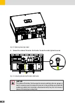
Fig. 20: Locking the cable glands
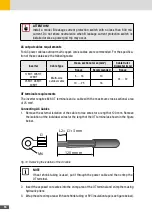
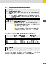
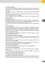
4. Check with a voltmeter of proper scale that the polarities and the DC voltage values are
correct.
RANGE
MAXMI N
REL
Hz %
P
C
800 00
Fig. 21: Checking DC voltage values with a voltmeter
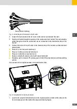
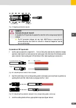
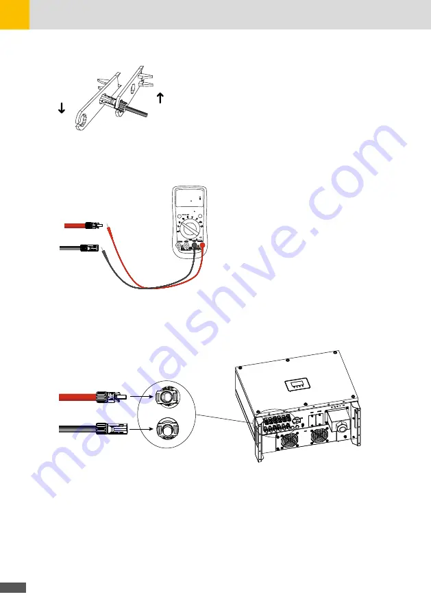
5. Insert the connectors into the respective counterparts located at the bottom of the inverter
and push them until they are locked by a “click” of the plastic side tabs.
PV–
PV+
P
C
Fig. 22: Connecting the assembled cable to the SHT inverter
6. After connecting the PV strings, ensure that all connectors are in position by checking for
resistance when a slight pull is applied.
5�3
Communication interface
WIFI module implements communication with cloud server through
wireless network to monitor PV inverter‘s data status.
For more details, refer to WIFI product application manual.
Содержание 17SHT
Страница 1: ...Instruction Manual SolarMax SHT series 17SHT 20SHT 22SHT 25SHT 28SHT 30SHT...
Страница 4: ...4...
Страница 39: ...39 en...


