


21
en
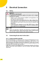
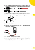
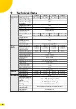
2. Insert the terminals in the corresponding plastic enclosures and lock them
in position by pushing them until the metal tabs are engaged with a “click”.
Fig. 17: Connecting the assembled connector to the corresponding plastic enclosures
3. Lock the cable glands with an appropriate torque (see figure below).
Fig. 18: Locking the cable glands
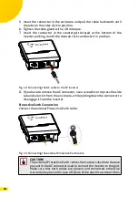
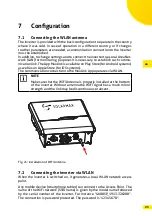
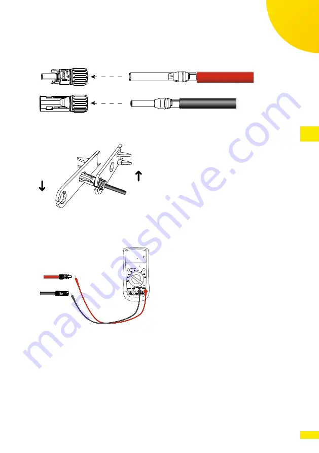
4. Check with a voltmeter of proper scale that the polarities and the DC
voltage values are correct.
RANGE
MAXMI N
REL
Hz %
P
C
800 00
Fig. 19: Checking DC voltage values with a voltmeter
5. Insert the connectors into the respective counterparts located at the
bottom of the inverter and push them until they are locked by a “click” of
the plastic side tabs.


