


10
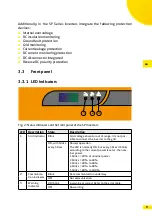
The following table shows the status of the LED indicators in case of a warning/
alarm:
Description
Grid
indicator
Comm�
indicator
Warning
indicator
Leakage current abnormal
Inverter relay abnormal
Insulation resistance abnormal
Leakage current HCT abnormal
Internal Communications Fault
Boost circuit abnormal
EEPROM fault
Flash programming
Other warning
Legend:
LED ON
LED OFF
LED Blink
keep original status
3�3�2 Display (optional)
Normal Operation
The SP units are equipped with a two-line LCD display. The LCD display shows
the parameters currently generated by the PV system on a rolling basis.
Warning/Alarm
In the event of faults, the following alarm codes are displayed:
Code
Meaning
Description
A00
Grid over voltage
The grid voltage exceeds the permitted
voltage range
A01
Grid under voltage
The grid voltage falls below the permitted
voltage range
A02
No grid
Grid voltage is 0 V
A03
Grid over frequency
The grid frequency exceeds the permitted
frequency range
A04
Grid under frequency
The grid frequency falls below the permitted
voltage range
A06
Grid unbalanced
The grid voltage unbalances are lie outside
the permitted voltage range.
B00
PV over voltage
The PV voltage exceeds the permitted voltage
range
B01
Insulation resistance
abnormal
The insulation resistance to ground is too low
when starting the inverter.


