SOLARMAX SP
3600SP / 4000SP / 4600SP / 5000SP
Instruction Manual
Страница 1: ...SOLARMAX SP 3600SP 4000SP 4600SP 5000SP Instruction Manual...
Страница 2: ...SOLARMAX GmbH Zur Sch nhalde 10 D 89352 Ellzee E Mail info solarmax com SOLARMAX GmbH 2021 SOLARMAX GmbH Zur Sch nhalde 10 D 89352 Ellzee E Mail info solarmax com SOLARMAX GmbH 2021...
Страница 3: ...4 2 Selecting the installation location 13 4 3 Mounting the inverter 14 5 Electrical Connection 16 5 1 Safety 16 5 2 Connecting the inverter to the mains 16 5 2 1 Integrated RCD and RCM 16 5 2 2 Conne...
Страница 4: ...4...
Страница 5: ...s and industrial electronics technicians 1 3 Where to keep this manual The plant operator must ensure that this instruction manual is available to the relevant persons at all times If this original do...
Страница 6: ...anger ously high DC voltage Make sure that all electrical input conductors to the inverter are de energized before starting any work on the inverter or the input conductors DANGER Fatal electric shock...
Страница 7: ...nce of the safety instruction may cause serious injuries Read and follow the operating instructions supplied with the inverter Do not remove any symbols on the inverter Replace damaged symbols CE mark...
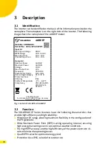
Страница 8: ...II Protective Class I IP Rating IP65 Ambient Temperature 25 60 C Compliancy VDE AR N 4105 VDE 0126 1 1 CEI 0 21 SOLARMAX GmbH Zur Sch nhalde 10 89352 Ellzee Germany www solarmax com Fig 1 Label of SOL...
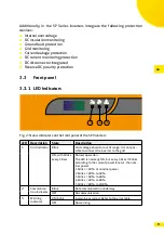
Страница 9: ...SP inverters LED Description State Description 1 Grid indicator Blink Grid voltage absent or out of range It is not pos sible to connect the inverter to the grid ON with blinks every 30sec Normal oper...
Страница 10: ...y the PV system on a rolling basis Warning Alarm In the event of faults the following alarm codes are displayed Code Meaning Description A00 Grid over voltage The grid voltage exceeds the permitted vo...
Страница 11: ...mitted voltage range B05 Weak irradiance The output of the PV modules is less than the minimal operating power B07 PV polarity reversed The poles of the PV strings are connected with reversed polarity...
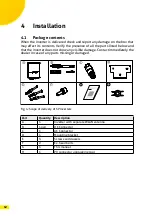
Страница 12: ...w and that the inverter does not show any visible damage Contact immediately the dealer in case of any parts missing or damaged G H Fig 4 Scope of delivery of SP inverters Part Quantity Description A...
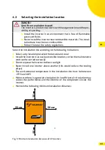
Страница 13: ...ions Select a dry location protected from water and snow Install the inverter in an easily accessible location so that the maintenance work can be carried out easily Do not expose the inverter to dire...
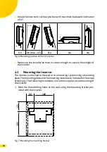
Страница 14: ...inverter 4 3 Mounting the inverter The inverter is attached to the wall or to a mounting system using a mounting plate The mounting plate and the mounting material are included in the scope of deliver...
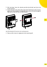
Страница 15: ...up the slots on the sides of the heatsink with the hooks on the bracket adjust until the coupling is completely done and use the two hexagonal head bolts to lock the inverter to the bracket Fig 8 Moun...
Страница 16: ...electric arcs could develop NOTE Follow the applicable standards and regulations to implement the electrical connections in particular for the section of the conduc tors the fuses and the Protective E...
Страница 17: ...ve the isolation of the individual wires for a length X of about 10 15 mm y x N L Fig 9 Removing the isolation of the AC cable 2 Crimp or solder tip terminals on the wires N L Fig 10 Connecting the ti...
Страница 18: ...to remove the AC connector use a screwdriver to press the side tab and unlock it from the enclosure while pulling down the connector to disengage it from the inverter Protective Earth Connection Conne...
Страница 19: ...his inverter is equipped with two MPPT circuits having the following charac teristics Model Max DC Voltage Max DC Current MPP1 MPP2 3600SP 600V 26 A 2 x 13 A 4000SP 600V 26 A 2 x 13 A 4600SP 600V 26 A...
Страница 20: ...age The PV generator voltages are very high NEVER plug or unplug the DC connectors when the inverter is turned on oth erwise dangerous electric arcs could develop Connection of PV input cable 1 Cut th...
Страница 21: ...e cable glands with an appropriate torque see figure below Fig 18 Locking the cable glands 4 Check with a voltmeter of proper scale that the polarities and the DC voltage values are correct R A N G E...
Страница 22: ...Switch on the external switch of the AC feed line connecting the inverter to the grid 3 Observe the status of LED indicators on the inverter according to the table described in Section 3 3 When the LE...
Страница 23: ...ems as well as on Apple Store for iOS systems The communication connection to the MaxLink App operates via WLAN NOTE Make sure that the WiFi Antenna is properly installed at the bottom of the inverter...
Страница 24: ...verter configuration The MaxLinkApp establishes the communication with the inverter and down loads the data Data are displayed on the screen Inverter is not available at the App MaxLink If connected i...
Страница 25: ...the configuration of the inverter e g national standards power factor derated power 1 Select the Setting button in MaxLink see below Fig 23 Overview of the MaxLink App 2 Select Setting in the selecti...
Страница 26: ...4 Enter the administrator password to change inverter data Use the pass word admin see the following figure 5 Select buttton Login as Administrator Fig 26 Login to the inverter 6 If the login was succ...
Страница 27: ...tings CAUTION Inverter settings have to be conform to the specifications of the local energy provider 7 To change the inverter settings select the selection field Standard Code The following selection...
Страница 28: ...28 Fig 28 Standard code inverter settings 8 Select the standard code of your local energy provider...
Страница 29: ...xpectations Check that the inverter has enough air circulation and that it is not under direct sunlight Check that the heatsink is clean and not obstructed Check the configuration of the PV generator...
Страница 30: ...000 W 4 600 W 5 000 W Maximum output apparent power 3 680 VA 4 400 VA 4 600 VA 5 000 VA Maximum AC current 16 0 A 19 1 A 22 0 A 23 8 A Mains nominal voltage 230 V Mains voltage range 160 V 300 V Mains...
Страница 31: ...C62116 VDE 0126 1 1 CEI 0 21 Device safety IEC 62109 1 IEC 62109 2 Interfaces Data communication Integrated WLAN Optional GPRS RS485 Weight and dimensions Weight 12 8 kg Dimensions W x H x D 335 x 426...
Страница 32: ...LARMAX Central Inverters Series C S TS TS SV 24 months from purchase date but max 30 months after delivery of device by SOLARMAX Series RX 60 months from purchase date but max 66 months after delivery...
Страница 33: ...uthorized to install the device which needs to be replaced with a com parable device with an equivalent or higher performance Necessary technical adjust ments of the replacement device for the install...
Страница 34: ...MAX will not be compensated In case of neglecting this procedure SOLARMAX reserves the right to decline the delivery of of the guarantee service 6 Exclusion of Guarantee SOLARMAX reserves the right t...
Страница 35: ...and the payment by the customer Deviating written confirmation from SOLARMAX have priority 8 Conditions after the Extension of the Guarantee The cost for repair and replacement after the extension of...
Страница 36: ...nter You will find all contact information on our website www solarmax com Hotline DE 49 8283997902810 CH 41 315281165 ES 34 932203859 GB 44 2038080346 IT 39 0418520076 FR 33 820420684 Fax 49 82839979...