


Figure 30: Inserting the Ethernet (CAT6) cable
8. Route the Ethernet cable to the communication board and plug to the LAN port.
9. Crimp an RJ45 plug on the Ethernet cable.
10. Tighten the gland nut with a torque of .
11. Close the cover of the communication board compartment.
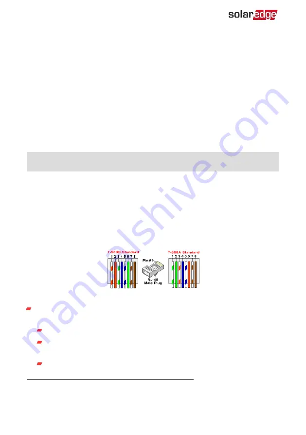
Ethernet (CAT6) Cables
CAT6 cables have eight wires (four twisted pairs), as shown in the pin layout of the
Figure 31. Wire colors may differ from one cable to another. You
can use either wiring standard, as long as both sides of the cable have the same pin-out
and color-coding.
RJ45 Pin #
Wire Color
(1)
10Base-T Signal
100Base-TX Signal
T568B
T568A
1
White/Orange
White/Green
T
2
Orange
Green
Transmit-
3
White/Green
White/Orange
4
Blue
Blue
Reserved
5
White/Blue
White/Blue
Reserved
6
Green
Orange
Received-
7
White/Brown
White/Brown
Reserved
8
Brown
Brown
Reserved
Figure 31: Ethernet connector - pin layout
Use a non-crimped cable to connect via the gland to the RJ45 port on the inverter's
communication board or, if using a spool of cable, connect as follows:
Insert the cable through the gland.
Remove the cable’s external insulation using a crimping tool or cable cutter and
expose eight wires.
Insert the eight wires into an RJ45 connector, as shown in
(1)
The connection does not support RX/TX polarity change. Supporting crossover Ethernet cables depends
on the switch capabilities.
Three Phase Inverters with Synergy Technology
56
Creating an Local Area Network (LAN) Connection
Содержание SE K Series
Страница 74: ......


