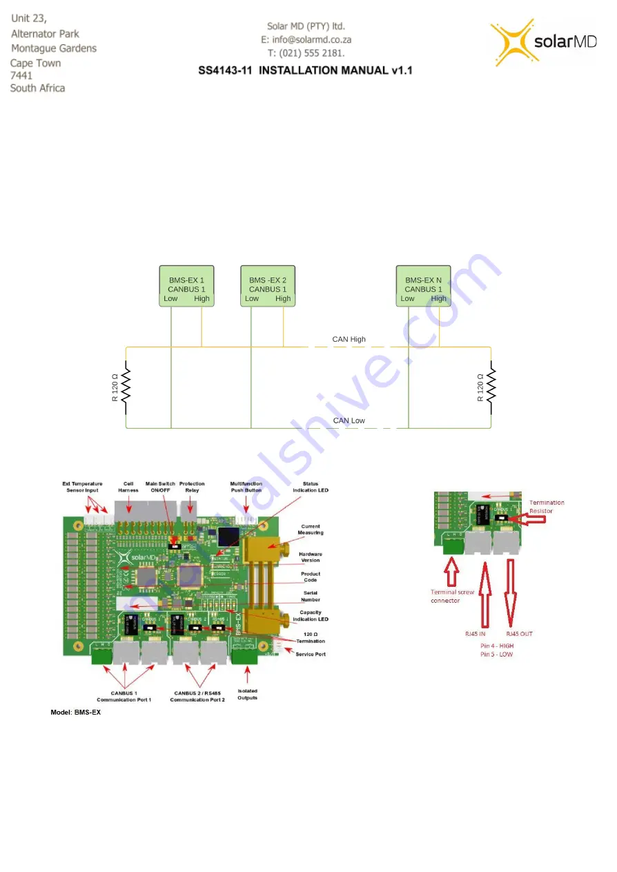
Each interface has two indication LEDs which indicate traffic
-
Flash Orange 0.5s:
Broadcasting, No communication active
-
Flash Orange 0.1s:
Establishing communication
-
Green:
Line connected
For stable communication a 120
Ω termination selector switch is mounted on the board for each
interface.
**Note: The first and last device in a chain should have terminations ON.
Figure 10: BMS communication ports
24
Содержание SS4143-11
Страница 1: ...INSTALLATION MANUAL SS4143 11 Advanced Lithium Ion battery 0 ...
Страница 6: ...Mechanical installation 5 ...
Страница 7: ...Installing top cover plate Figure 3a Top cover installation single or multiple batteries in line 6 ...
Страница 8: ...Figure 3b Battery spacing installation single or multiple batteries in line 7 ...
Страница 9: ...Figure 3c Battery feet installation of battery feet 8 ...
Страница 38: ...Annex A BMS EX Inverter Charger control and Cluster operation 37 ...
Страница 44: ...3 1 3 3 Multiple inverters multiple batteries 43 ...
Страница 47: ...Note The image below might differ depending on the firmware version of your inverter display 46 ...


