background image

19

S O L A   N e v e r   S t o p s   I n n o v a t i n g

ups 325

Appendix A: Adjusting Voltage Settings

When the unit is not sounding an alarm, you can use the button shown below to change the
following:
• Nominal  Voltage — The normal voltage the UPS is programmed to expect, and the nominal UPS

output voltage under line loss conditions.

• Buck — The input voltage at which the SOLA 325 decreases voltage before providing output

because the input voltage is too high.

• Boost — The input voltage at which the SOLA 325 increases voltage before providing output

because the input voltage is too low.

• Transfer to Inverter — The point at which the UPS switches to inverter (battery power), either

because AC input voltage is very low or because it is very high.

Note:

Make sure you want to change these values before you start the procedure below. Once
you press the button shown for 10 seconds, the values will change to the default values,
and any previous changes you have made will be lost. If you have questions, contact the
nearest Sola office, or call National Service and Repair Centre on: 1800 034 401 (except
Melbourne); 9768 3105 (Melbourne only).

Do not change voltage settings when unit is operating on
inverter. To change the values, follow these steps:

1.

Press the button shown until the LEDs on the front of the
SOLA 325 blink (approximately 10 seconds). After the
LEDs blink, three or four will stay lit, and the SOLA 325
beeps for one second.

2.

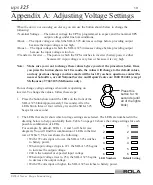
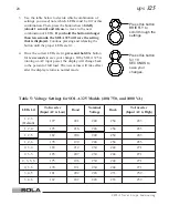
The LEDs that are lit show which voltage settings are selected. The LEDs are numbered in the
drawing below to help you identify them. Table 5 on page 18 shows the voltage settings for each
possible combination of LEDs.
For example, by default, LEDs 1, 2, and 3 will be lit (see
diagram). You will find this combination of LEDs in the first
row of Table 5. This row shows the following:

• With 197 volts input or lower, the SOLA 325 switches

to battery power.

• When input voltage drops to 221, the SOLA 325 begins

to increase the output voltage.

• 240 is the nominal or expected input voltage.
• When input voltage rises to 254, the SOLA 325 begins

to decrease the output voltage.

• With 283 volts input or higher, the SOLA 325 switches to battery power.

Press this
button for 10
seconds (until
all of the lights
blink).

1

2

3

4

5

6

1

2

3

4

5

6

LED Numbers

Default Setting

Содержание UPS 325

Страница 1: ...USER GUIDE ups 325 400 VA 750 VA and 1000 VA A Company ...

Страница 2: ...nt generated by the UPS This UPS generates no more than 1 mA of current To limit the total leakage current to 3 5 mA the load leakage must be limited to 2 5 mA The three wire receptacle that you plug the UPS into must have a good low impedance ground protective earth connection to provide a safe path for leakage current ...

Страница 3: ...u p s 325 400 VA 750 VA and 1000 VA User Guide STM 0302B Copyright 1999 Best Power All rights reserved ...

Страница 4: ...his happens we will give you a Return Authorization RA number When you return a SOLA 325 to the factory for any reason please use the original packing material in which your unit was shipped to you You may be responsible for repair charges for shipping damaged units which are not packed in SOLA packing material If you have discarded the original packing material please call the nearest SOLA office...

Страница 5: ...ries 9 Battery Replacement Instructions 400VA Model 10 Battery Replacement Instructions 750VA and 1000VA Models 11 Communication Port 12 Pinouts 12 Specifications 13 Warranty 14 Appendix A Adjusting Voltage Settings 19 SOLA Australia Offices 21 Trademarks Windows is a registered trademark of Microsoft Corporation All other brand and product names are trademarks or registered trademarks of their re...

Страница 6: ...elsius recharge the batteries more often CAUTION Whenever the unit s On Off switch is On there may be dangerous voltage present at the unit s outlets This is because the unit s battery supplies power even if the unit is not plugged into the wall outlet The unit contains dangerous voltages To reduce the risk of electric shock install in a temperature controlled and humidity controlled indoor area f...

Страница 7: ...ble alarm keep you aware of the unit s status Use the drawings below to identify features of the unit Controls and Indicators Line Buck boost 400VA Model Battery Mode Load or Battery Charge see page 6 Alarm Program Button On Standby Button Front and Side Views Back Views Network Surge Protection DB9 Communication Port Output Receptacles 2 Input Connector Fuse 750VA and 1000VA Models Network Surge ...

Страница 8: ... in the battery After the battery test the top green light should remain on If the unit beeps or if the top light does not remain on even though input power is available from the wall outlet go to the Troubleshooting section 4 Switch off the equipment you want to protect and plug it into the outlets on the back of the SOLA 325 5 Switch on the protected equipment one at a time If the UPS beeps an a...

Страница 9: ...s 325 Installing CheckUPS II Software Your UPS is supplied with a CD ROM and communications cable to install and operate CheckUPS II To install CheckUPS II on your computer follow the installation instructions enclosed with the CD ROM ...

Страница 10: ...he unit beeps whenever the unit is on battery power or an alarm is present See Table 3 for information on beep coding In the figure below bucking means that SOLA 325 is reducing high input voltage and boosting means SOLA 325 is increasing low input voltage A B C D Steady SOLA 325 is operating on AC line Steady SOLA 325 is operating on batteries AC Line Operation A B C and D indicate percent of ful...

Страница 11: ...ll provide minimal backup time Replace the Battery The battery needs to be replaced See Replacing the Bat teries on page 10 To silence an alarm press the alarm silence button on the front panel see Page 3 for the location of this button The beep will stop but the alarm light will stay on Note Silencing the alarm does not solve the problem that caused it See Tables 3 and 4 If your SOLA 325 runs on ...

Страница 12: ...very second Plug the unit into a working wall outlet for at least 8 hours to allow the batteries to charge After recharge if the SOLA 325 will not operate on batteries or SOLA 325 beeps twice every 5 seconds on batteries phone SOLA Service Very low battery voltage Yellow BATTERY LED on green LINE LED off two beeps every ten seconds Use the unit on utility power wait for full recharge The beeps aut...

Страница 13: ... these objects could fall into the UPS Never allow any tool to contact both a battery terminal and the UPS cabinet or another battery terminal Do not lay tools or metal parts on top of batteries To ensure continued superior performance of your UPS and to maintain proper charger operation you must replace the UPS batteries with the same number and type of batteries These batteries must be the same ...

Страница 14: ...rd 3 On the bottom of the SOLA 325 remove the Phillips screw at the top of the battery door and slide the door off 4 Use the flap attached to the battery to lift it out of the unit 5 Disconnect the battery cables from the old batttery Dispose of the old battery properly 6 Connect the battery cables to the new battery red to positive black to negative Carefully install the battery back in to the SO...

Страница 15: ...on cable attached on top of the unit so it is out of your way while replacing the batteries 4 Remove the two screws from the interior panel to gain access to the batteries 5 Disconnect the red and black cables from the used battery pack 6 Use the tabs attached to the batteries to remove the batteries from the SOLA 325 7 Slide the new batteries into the unit Recon nect the cables to the new battery...

Страница 16: ...o Common after the UPS switches to battery power Pin 4 Common The signal ground for all signal pins Pin 5 Normally Open Low Battery Alarm Contact A normally open contact that closes pulls to Common during a Low Battery Alarm This tells CheckUPS II and other shutdown software when to start a computer shutdown Pin 6 Plug and Play Sense for Windows 95 Pin 7 Remote Shutdown Shorting this pin to Common...

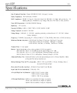
Страница 17: ... minutes 1000VA Model Full load 4 5 minutes Half load 15 minutes Transfer Time 2 6 ms typical Battery Sealed maintenance free valve regulated UL 924 recognized 400 VA Models One 12 V 9 0 AH batteries Nominal Voltage is 12 VDC 750 VA Models Two 12 V 7 0 7 2 AH batteries Nominal Voltage is 24 VDC 1000 VA Models Three 6 V 12 0 AH batteries Nominal Voltage is 18 VDC Automatic Battery Test Automatic ba...

Страница 18: ... VA 213 x 163 x 363 mm Weight 400 7 5 kg 750 14 kg 1000 16 kg SOLA reserves the right to change specifications without prior notice Warranty Warranty Information This Warranty is subject to SOLA s standard Conditions of Sale which govern all sales of products by SOLA Australia Ltd 1 SOLA products in general are warranted against failure due to faulty materials and or workmanship for a period of tw...

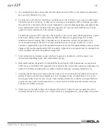
Страница 19: ...event shipping damages and pay freight charges to the location nominated by SOLA Australia Approval to return goods must be obtained from SOLA Australia Ltd before the goods are despatched 5 Units returned for in warranty repairs which are found not to be defective will be subject to an inspection and handling charge plus transportation charges 6 High grade batteries designed for Uninterruptible P...

Страница 20: ...This page intentionally left blank ...

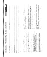
Страница 21: ... Yes you will receive mail from SOLA at least three 3 times per year q No 1 Where did you purchase this SOLA UPS from q Retail Store q Computer Store q SOLA Distributor q Direct from SOLA q Electrical Wholesaler q Mail Order Catalogue q Internet q Other 2 Why did you purchase a SOLA UPS Check all that apply q Recommendation q Reputation q After Purchase Support q Features q Price q Other 3 What pr...

Страница 22: ...SOLA Australia Ltd 13 Healey Road DANDENONG VIC 3175 AUSTRALIA AFFIX P OSTAGE STAMP ...

Страница 23: ...ice and Repair Centre on 1800 034 401 except Melbourne 9768 3105 Melbourne only Do not change voltage settings when unit is operating on inverter To change the values follow these steps 1 Press the button shown until the LEDs on the front of the SOLA 325 blink approximately 10 seconds After the LEDs blink three or four will stay lit and the SOLA 325 beeps for one second 2 The LEDs that are lit sho...

Страница 24: ...ur changes If the SOLA 325 is running on AC input power the display will change back to the percent of full load The new values will take effect after the display returns to normal mode Press this button for 10 SECONDS to save your changes Press this button BRIEFLY to scroll through the settings LEDs Lit To Inverter Input AC is Low Boost Nominal Voltage Buck To Inverter Input AC is High 1 2 3 Defa...

Страница 25: ...cept Melbourne 9768 3105 Melbourne only Customer Service Offices Adelaide PO Box 481 Marlestone Business Centre SA 5033 Phone 08 8347 3622 Fax 08 8445 6328 Brisbane Unit 2 8 Lockhart Street Woolloongabba QLD 4102 Phone 07 3891 1211 Fax 07 3891 2492 Perth Unit 2 321 Great Eastern Highway Redcliffe WA 6104 Phone 08 9478 3511 Fax 08 9479 4577 Sydney 67A Ryedale Road West Ryde NSW 2093 Phone 02 9949 6...

Страница 26: ...ld sales offices are conveniently located to provide prompt attention to customer needs Call SOLA direct to find the location of your closest authorised distributor SOLA BEST Offices SOLA Australia Ltd Best Power Best Power Technology Limited 13 Healey Road P O Box 280 BEST House Dandenong Victoria 3175 Necedah Wisconsin 54646 U S A Wykeham Industrial Estate AUSTRALIA Telephone 1 608 565 7200 Moor...

Отзывы: