


Page: 3
Status LED
Status
off
no power or in reset state
flashing green
in initialization state
solid green
CAN started
flashing red
CAN error passive
solid red
CAN bus off
1.4 Driver configuration
CAN-PRO2-PCIE is recognized by the driver automatically. Nothing more is usually required.
However, advanced configuration – like changing the name of a CAN channel or setting a
default baudrate - is possible with the Softing CAN Interface Manager.
•
Click
Start – All Programs – CAN – Runtime System Configuration – Softing CAN
Interface Manager (SCIM)
•
For more details on the driver configuration click
Start – All Programs – CAN – Runtime System Configuration – SCIM_Manual
1.5 Application Software
How to use CAN-PRO2-PCIE and how to write application software, is described in the
Software Manual.
•
To open this manual click
Start – All Programs – CAN – CAN_API - DOC – Softing Layer2
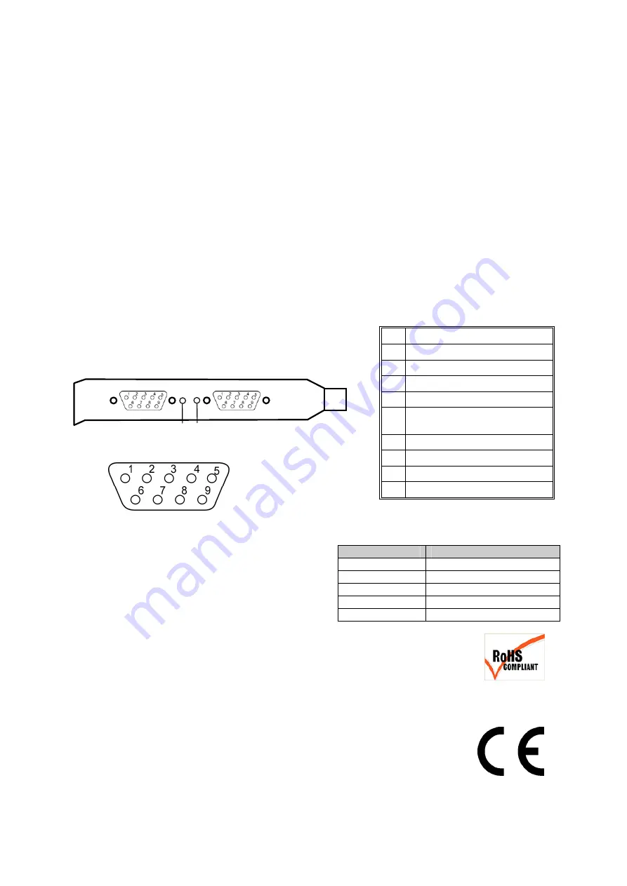
2 CAN Connector Pin Assignment
Connector pinning complies to CiA standard DS 102.
Pinning of the 9 pin
D-Sub
connector
3 Status
LEDs
Each CAN channel has a status LED that
shows its current status .
4 RoHS
Information
CAN-PRO2-PCIE is RoHS compliant.
5 CE
Information
This device complies with the requirements of the EC directive 2004/108/EC
"Electromagnetic Compatibility" (EMC directive).
The product meets the following requirements:
•
Emission: EN55022 Class B (ITE Product Standard)
•
Immunity: EN61000-6-2 Generic Immunity Standard (industrial environments)
Pin Signal
1 N.C.
2 CAN_L
3
Isolated GND
4 N.C.
5
Drain connected to connector
shield (1M/2.2n to isolated GND)
6 Isolated
GND
7 CAN_H
8 N.C.
9 N.C.
CAN2
CAN1
L2 L1


