background image

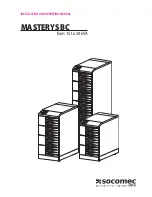
MASTERYS BC

from 15 to 20 kVA

10

IT

ALIANOENGLISH

UNPACKING AND INSTALLATION 

OF THE UNIT

3

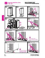
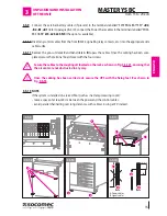
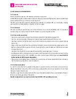
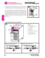
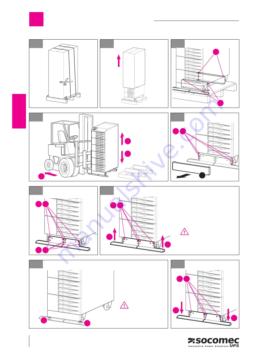
3.2.2 Models “T” (h 1.400 mm).

3.2.2-9

3.2.2-6

Loosen screws 

B

.

Remove screws 

C

.

3.2.2-7

Tighten screws 

B

1

B

2

C

2

B

1

1

The UPS can be moved.
Place the UPS in the installation 
area.

3.2.2-8

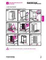
Secure the UPS with feet 

D

.

D

D

Secure the UPS with feet 

D


only when it is in position 
with the cable connected.

Loosen screws 

B

1

B

2

2

3.2.2-4

1

3

2

3.2.2-5

Remove screws 

A

.

1

A

2

3.2.2-2

3.2.2-1

3.2.2-3

Remove screws 

A

 and screws 

B

.

A

B

Содержание Masterys MAS2BC115M+D1

Страница 1: ...INSTALLATION AND OPERATING MANUAL MASTERYS BC from 15 to 20 kVA...

Страница 2: ...ITALIANO...

Страница 3: ...enerator 16 3 7 External E S D connection 16 3 8 Connecting the UPS to an internal isolation transformer 16 3 9 UPS Parallel configuration 17 3 9 1 General 17 3 9 2 Installation 17 3 9 3 Power cable c...

Страница 4: ...SW options 34 9 PROBLEM SOLVING 36 9 1 System alarms 36 9 2 UPS alarms 37 9 3 Preventive maintenance 38 9 3 1 Batteries 38 9 3 2 Fans 38 9 3 3 Capacitors 39 10 OPTIONS 40 10 1 ADC card 40 10 1 1 ADC...

Страница 5: ...ed load batteries Insufficient or inadequate maintenance Attempted maintenance repairs or modifications not carried out by SOCOMEC UPS personnel or personnel from a support centre authorised by SOCOME...

Страница 6: ...ust be repaired only by authorised technicians that have been specially trained for this purpose This equipment conforms to the European Community directives for professional equipment and bears the a...

Страница 7: ...rty the products may have to be adapted For such uses we would advise you to contact SOCOMEC UPS beforehand to confirm the ability of these prod ucts to meet the requested level of safety performance...

Страница 8: ...the weight of the UPS and of the battery cabinet if used Avoid pressing on the front panels when moving the unit The UPS MUST only be moved by two people at least The people MUST take position at the...

Страница 9: ...m and models M h 1 000 mm 3 UNPACKING AND INSTALLATION OFTHE UNIT Secure the UPS with feet D only when it is in position with cables connected 3 2 1 5 3 2 1 2 3 2 1 1 3 2 1 8 3 2 1 3 3 2 1 4 Remove sc...

Страница 10: ...screws C 3 2 2 7 Tighten screws B 1 B 2 C 2 B 1 1 The UPS can be moved Place the UPS in the installation area 3 2 2 8 Secure the UPS with feet D D D Secure the UPS with feet D only when it is in posi...

Страница 11: ...ack for adequate ventilation see figure 3 3 1 The UPS switches are accessed from the front however a space of at least 1 5 metres should be left at the front of the UPS for maintenance purposes It is...

Страница 12: ...of the input protection devices UPS Magneto thermal Magneto thermal Differential Input Output Battery Battery input1 Aux Mains1 input5 cable core size cable core size protection4 kVA A A A mm2 mm2 A...

Страница 13: ...n the connection and the type of remote switch please read paragraph 10 6 of this manual ATTENTION The neutral is not disconnected as even in the event of a single fault on the UPS it never has high p...

Страница 14: ...VA single phase output it is essential to connect the auxiliary mains to the relative dedicat ed terminal board If there is no separate mains for the bypass it is advisable to obtain one from the prim...

Страница 15: ...ted secure the terminal board cover with the four screws Secure the cables to the couplings D located on the rack as shown in Fig 3 5 121 ensuring that the air vents are not obstructed in any way Once...

Страница 16: ...ANSFORMER The MASTERYSTM IP model of the MASTERYSTM range is fitted with an internal isolation transformer If an external isolation transformer cabinet is required the following instructions should be...

Страница 17: ...ength must be used for the distribution connection between the general power switch A the switches C and the respective UPS units The length of the cables from A to each UPS must not exceed 25 meters...

Страница 18: ...TALLATION OFTHE UNIT 3 3 9 4 1 25 m max 15 m max RECOMMENDED PARALLEL CONFIGURATION A Main differential magneto thermal switch B Parallel bus cable C Single UPS magneto thermal switch if a separate au...

Страница 19: ...er the overload disappears when the voltage generated by the inverter goes is out of tolerances due to a major overload or a fault on the inverter wWhen the internal temperature exceeds the maximum va...

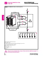
Страница 20: ...st By pass panel connection diagram If the UPS has an input for the auxiliary power supply the Q2 switch must be connected to this input and the main power supply input must be disconnected on the con...

Страница 21: ...ERYS can be operated in conjunction with a generator GE With a generator the frequency and voltage ranges of the auxiliary mains can be increased to accept the in stability of the GE and at the same t...

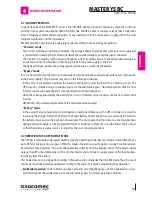
Страница 22: ...e connectors and the slots for the optional signalling cards Please refer to the relevant chapter for more details on the connection and use of the related communication interfaces cards 5 1 IDENTIFYI...

Страница 23: ...f the UPS for a continuous power supply to the load Position 2 MANUAL BY PASS This position should only be selected for ordinary or extraordinary mainte nance operations manual bypass the load is conn...

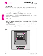
Страница 24: ...dentifies the condition of the power supply to the load C Alphanumeric information that uses a menu layout to provide details on any alarms that may occur and on the measurements controls and paramete...

Страница 25: ...failure or fault Off Inverter off or power supply from automatic bypass LED L4 GREEN On Auxiliary input mains present and ok Flashing Auxiliary input mains out of tolerance Off Auxiliary input mains n...

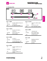
Страница 26: ...Load powered by the inverter or in high efficiency mode 6 1 2 Meaning of the status light bar The light bar B figure 6 1 1 provides an immediate indication of the condition of the power supply to the...

Страница 27: ...by the rectifier have been exceeded A23 RECTIFIER ALARM Rectifier fault A25 INVERTER ALARM Inverter fault A26 BATT CHARGER ALM Battery charger fault A29 BY PASS ALARM Bypass fault A30 OVERLOAD STOP Th...

Страница 28: ...mands can also be sent for diagnostic purposes by means of the extended commands menu if enabled in the configurations menu The command is activated by selecting it with the UP e DOWN keys press ENTER...

Страница 29: ...Selects the type of batteries used Sealed SET BATTERY CAPACITY Sets the battery capacity in Ah 9 5 1000 Ah SET CHARGERTYPE Selects the type of recharge required Auto Float int SET BATTERY ELEMENTS Se...

Страница 30: ...plete the start up procedure 5 3WARRANTY CD ENT PROCEDURE The activation code is provided directly by the reference Support Centre upon communication of the serial number of the equipment which is dis...

Страница 31: ...pply to the load and stops the UPS and the battery charger Activate the stop procedure from the COMMANDS menu on the mimic panel wait approx 2 minutes for shutdown the controlled shutdown of any serve...

Страница 32: ...to position 1 input mains ON Set switch Q1 and or the external battery switches to position 1 battery circuit closed Activate the start procedure from the commands menu on the mimic panel From the mi...

Страница 33: ...on channels and external devices As each channel is independent simultaneous connections can be made to satisfy the different levels of signal ling and remote monitoring See the options paragraph to a...

Страница 34: ...to the local network It is normally used on medium large complex networks and in multi server environments where the IT manager centrally controls all the network resources The physical position of th...

Страница 35: ...NetVision via the mail server on the same network Any emergency situation is managed and resolved extremely quickly and remotely by the Support Centre with immediate intervention on site if needed The...

Страница 36: ...see the technical speci fications The frequency is subject to continuous variations typical with power supplied from an incorrectly sized GE A07 temperature over the limits The technical plant tempera...

Страница 37: ...PS and reset the alarms A20 wrong configuration Error in the configuration parameters contact the support service A30 block due to overload Reduce the load rate applied to the UPS and reset the alarms...

Страница 38: ...al time and the recharging and discharging procedures are selected automatically in order to optimise battery life expectancy and offer maximum performance Furthermore during the operating life of the...

Страница 39: ...inverter section and filtering capacitors used in the output section whose life is dependent on using and environmental conditions The average expected life of these components is shown below Electro...

Страница 40: ...1 OFF OFF In 3 Isolation controller 2 Mode 2 POWER SAFE configuration Position IN OUT Description Filter dip1 dip2 level ON OFF Out 1 General Alarm 2 ON OFF Out 2 Power safe plug 1 2 ON OFF Out 3 Pow...

Страница 41: ...ge on the mimic panel Description of signals Message on the mimic panel Description General Alarm General alarm contact output No Alarm NO contact closed NC contact open Alarm NO contact open NC conta...

Страница 42: ...hts must be carried out only by speciallytrainedSOCOMECUPSstaff Standard In standard configuration the load connected to the POWER SHARE plug is disconnected if one of the follow ing conditions is ver...

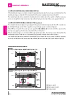
Страница 43: ...feed of dangerous voltages on the power line or if it is a separate line on the auxiliary back up power supply line The BKF card shown in figure 10 6 1 is used to control the external device The BKF P...

Страница 44: ...31 N1 Backup power source M1 Input power terminal board M2 Backup power terminal board T1 Remote switch1 T2 Remote switch1 Q1 Input power switch Q2 Backup power switch XB1 Connector on BKF PCB XB2 Con...

Страница 45: ...ry time there is a power failure Should the Neutral potential be very high due to certain error conditions or due to installations downstream e g ground fault not detected and protected high dispersio...

Страница 46: ...ax Acoustic noise dB 55 Required cooling capacity m3 h 546 Dissipated power max W 1 187 1 187 1 738 1 738 Dissipated power BTU h 4 051 4 051 5 933 5 933 Electrical specifications Input 15 15 20 20 Mai...

Страница 47: ...44x795x1 400 415 MAS2BC115T C4 3 1 15 444x795x1 400 520 MAS2BC120M D1 3 1 20 444x795x1 000 240 MAS2BC120M C2 3 1 20 444x795x1 000 310 MAS2BC120T D2 3 1 20 444x795x1 400 390 MAS2BC120T D3 3 1 20 444x79...

Страница 48: ...ITALIANO FRAN AIS...

Отзывы: