8
MASTERYS
BC 60-80 kVA - Ref.: IOMMASBCXX06-EN 06
2. UNPACKING AND INSTALLATION OF THE UNIT
2.3.1. Backfeed
protection
If the UPS does not have an automatic protection device against current backfeed, the operator/installer must add a warning
label to all the mains power disconnecting switches installed at a distance from the UPS area. This serves to remind technicians
of the fact that the circuit is connected to a UPS (see the SAFETY section in paragraph 1 of this manual and paragraph 4.7.3 of
the EN62040-1 2009-05 standard).
The label is supplied with the system.
The backfeed protection device may be built into the system (only on specific request), or an electromechanical switch may be
installed externally in the input of the UPS.
• If the UPS incorporates this protection, proceed with the connections as described in paragraph 2.5 of this manual.
• To install the external backfeed protection it is necessary to use the BKF card and an external electromechanical switch that
should be installed as close as possible to the UPS. For further information on the connection and the type of remote switch,
please read paragraph 9.7 of this manual.
WARNING
The neutral is not disconnected as, even in the event of a single fault on the UPS, it never has high potential when
the mains and/or auxiliary power supplies are disconnected upstream. This is to prevent transformation of the
power source to the UPS every time there is a power failure.
Should the neutral potential be very high due to certain error conditions or due to installations downstream (e.g.
ground fault not detected and protected, high dispersion of a phase, or the IT system), it will be necessary to install
either devices that disconnect the Neutral or alternatively a system that detects, signals and protects against high
neutral/ground potential that could lead to UPS failure.
NOTE
For equipment with separate Emergency Mains, it must be possible to make the neutral of the Emergency Mains
line electrically common with the neutral of the main input feed line.
2.4. INSTALLATION PROCEDURES AND INSTRUCTIONS
The procedure below should be followed closely for correct installation:
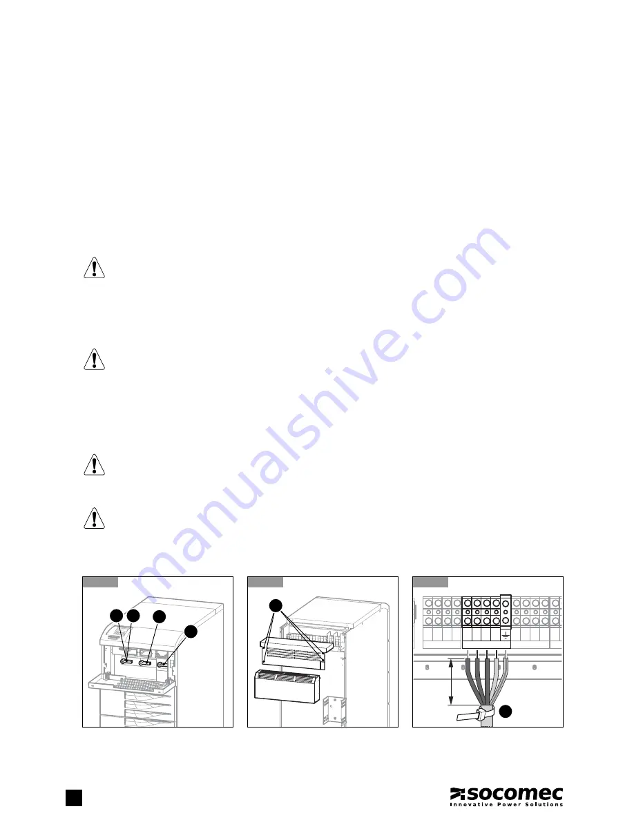
2.4-1
Set
switches
Q2/Q4, Q3, Q5
to position
0
, open the switches of any external battery cabinets.
Switch off the UPS, remove the power, open the switches of any external battery cabinets, isolate the system and
wait for 5 minutes before working on the terminal board or any internal UPS parts.
2.4-2
Open the terminal board protection panel at the back of the UPS by removing the four fastening screws
A
.
The terminal board shown is the most complete version including all options. On basic models or models with inter-
nal batteries the terminal board has fewer terminals. Refer to the names of each terminal to identify it during
connection. After connection secure the cables with bands C (figure 2.4-3) to couplings B as shown in the figure 2.4-6.
2.4-3
Connect the ground lead to the terminal with the corresponding symbol. Connect the input cables to the terminals labelled
MAINS SUPPLY
L1, L2, L3, N
(observing the phase cycle direction).
2.4-1
Q2 Q4
Q5
Q3
2.4-2
A
2.4-3
OUTPUT
L12 L22 L32 N2
EXTER
+B2
AUX MAINS SUPPLY
L11 L21 L31 N1
MAINS SUPPLY
L1 L2 L3 N
8 cm max
C


