© Trynex International 2009 L1102
5 — 28
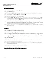
Mounting Instructions
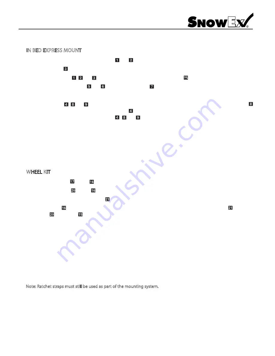
IN BED EXPRESS MOUNT
Step 1:
Locate left and right side mounting rail and .
Step 2:
Locate item cross rails.
Step 3:
Assemble items , and together per exploded view. (Accessory Shim may be needed for adjustment.)
Step 4:
Install rear latches items and with 5/8" thin lock nut .
Step 5:
Place frame assembly on truck and center left to right.
Step 6:
Install items , and per illustration.
Note: on older models, you will have to drill out frame to accept item
stop bolt. To do this, you will need to bolt item to lower frame rail using a drill template to locate the bracket,
drill all four holes and then install items , and .
Step 7:
Determine front to back location by either placing spreader into locked position on frame assembly or by
measuring using rear side frame holes and measuring to rear of pick up bed. Mark holes with paint marker or scribe.
Verify that there are no critical components below the pick up bed such as a gas tank, etc.
Step 8:
Drill holes and mount frame using supplied 5/8" hardware.
Note: There are alternate holes for drilling around items
that may be in the way.
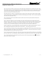
WHEEL KIT
Step 1:
Assemble item to item using supplied hardware.
Step 2:
Assemble items to item using supplied hardware.
Step 3:
With spreader in truck, place item
wheel arm on the rear center of upper rail of hopper (see illustration/pictures.)
Step 4:
Place item
on auger weldment and trap the lower edge while at the same time positioning item to engage
item so that item pin with ring can keep the two assemblies together.
Step 5:
Lock swivel wheels.
Step 6:
Pull spreader back and off the in bed mount, allow spreader to rotate towards ground with the locked wheels
touching first.
Step 7:
Continue to pull spreader into a vertical position.
Step 8:
When everything is stable, release wheel locks and slowly move spreader to storage location. Lock wheels when
final place has been established.
Step 9:
See photo and drawing illustrations for assembly and installation.
Note: Ratchet straps must still be used as part of the mounting system.
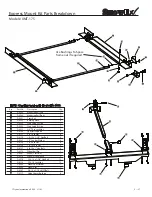
Model # XMT-175
Содержание Vee Pro 3000
Страница 8: ...Trynex International 2009 L1102 5 8 Side and Bottom View Model SP 3000...
Страница 9: ...Trynex International 2009 L1102 5 9 Side and Bottom View Model SP 6000...
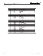
Страница 11: ...Trynex International 2009 L1102 5 11 Main Assembly Parts Breakdown Model SP 3000...
Страница 13: ...Trynex International 2009 L1102 5 13 Main Assembly Parts Breakdown Model SP 6000...
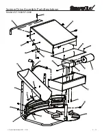
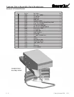
Страница 15: ...Trynex International 2009 L1102 5 15 Spinner Drive Assembly Parts Breakdown Model SP 3000 SP 6000...
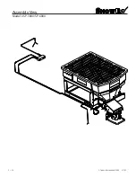
Страница 18: ...Trynex International 2009 L1102 5 18 Assembly View Model SP 3000 SP 6000...
Страница 39: ...THIS PAGE INTENTIONALLY LEFT BLANK Trynex International 2009 L1102 5 39...
Страница 40: ...THIS PAGE INTENTIONALLY LEFT BLANK Trynex International 2009 L1102 5 40...
Страница 41: ...THIS PAGE INTENTIONALLY LEFT BLANK Trynex International 2009 L1102 5 41...

