© Trynex International 2009 L1102
5 — 21
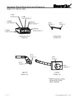
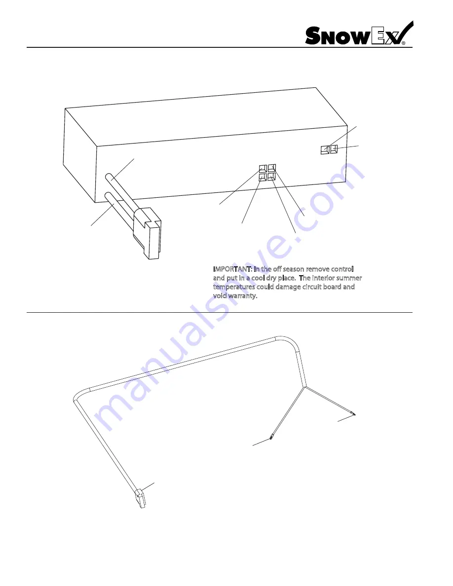
Black
Negative (–)
Auger
Red Positive (+)
Auger
Black Negative (–)
Spinner
Red Positive (+)
Spinner
Black Negative (–)
INPUT
OUTPUT
Red
Positive (+)
Vibrator
Black Negative (–)
Vibrator
Red Positive (+)
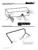
Controller Wiring Diagram
Connect to control
mating half
Positive
White with Red Tracer (+) to battery
Ring Terminal
Negative
Black (–) to battery
Ring Terminal
* NOTE:
A) Leads must only be attached to battery.
B) If fusing, must use minimum 60 Amp
Maxi type fuse or circuit breaker.
Control Power Cable
Model # SP-3000/SP-6000
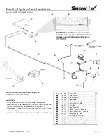
IMPORTANT: In the off season remove control
and put in a cool dry place. The interior summer
temperatures could damage circuit board and
void warranty.
Содержание Vee Pro 3000
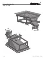
Страница 8: ...Trynex International 2009 L1102 5 8 Side and Bottom View Model SP 3000...
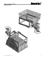
Страница 9: ...Trynex International 2009 L1102 5 9 Side and Bottom View Model SP 6000...
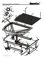
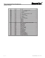
Страница 11: ...Trynex International 2009 L1102 5 11 Main Assembly Parts Breakdown Model SP 3000...
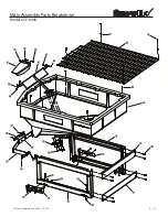
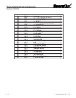
Страница 13: ...Trynex International 2009 L1102 5 13 Main Assembly Parts Breakdown Model SP 6000...
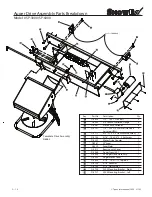
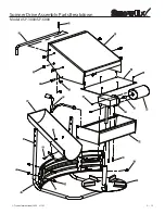
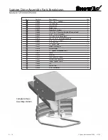
Страница 15: ...Trynex International 2009 L1102 5 15 Spinner Drive Assembly Parts Breakdown Model SP 3000 SP 6000...
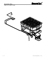
Страница 18: ...Trynex International 2009 L1102 5 18 Assembly View Model SP 3000 SP 6000...
Страница 39: ...THIS PAGE INTENTIONALLY LEFT BLANK Trynex International 2009 L1102 5 39...
Страница 40: ...THIS PAGE INTENTIONALLY LEFT BLANK Trynex International 2009 L1102 5 40...
Страница 41: ...THIS PAGE INTENTIONALLY LEFT BLANK Trynex International 2009 L1102 5 41...

