Snell IQOTR31 Скачать руководство пользователя страница 3

IQOTR31

www.snellgroup.com

Safety Information

Issue 1 Rev 1

Page 3

©

  2012 Snell Limited

Safety Information

Warnings

Notes

All lasers used in this product are Class 1, in 
accordance with EN60825-1 as well as 21CFR 
1040.10 and 1040.11.

Laser light can be damaging to the eyes. Optical 
fibers and uniters should be handled with great 
care.

The IQOTR31 is designed for use with Class 1 laser systems only. Ensure that all 
outputs do not exceed Class 1 as doing so will impair the safety of the system and 
may result in damage to the equipment.

Active fibers should not be handled unless their source can positively be identified 

as not exceeding Class 1 limits.

Note:

Optical uniters have shutters to prevent the ingress of dust. These shutters should 
only be opened when connecting optical fibers.

The ends of optical fibers should be cleaned with a liquid fiber cleaner, using a 
cotton bud, to ensure that there is no dust present before they are plugged in (the 
uniter is polarized).

Do not disturb or handle the optical fibers.

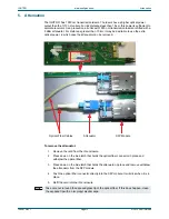
1550 nm Tx on the IQOTR31 module


An attenuator is required for short link distances (<15 km) and is fitted by default. 

For link distances greater than 15 km, the supplied attenuator may be removed to 
increase power. See “Attenuation” on page 13.

Содержание IQOTR31

Страница 1: ...snellgroup com User Instruction Manual IQOTR31 3G HD SD SDI Single Mode Fiber Optic Transceiver...

Страница 2: ...rates a policy of continuous improvement and development Snell reserves the right to make changes and improvements to any of the products described in this document without prior notice Contact Detail...

Страница 3: ...quipment Active fibers should not be handled unless their source can positively be identified as not exceeding Class 1 limits Note Optical uniters have shutters to prevent the ingress of dust These sh...

Страница 4: ...rom the RollCall Control Panel 14 6 1 Information Window 14 6 1 1 Unit Status 14 6 2 Inputs 14 6 2 1 Input 1 SDI Rate SDI IN 1 Input 2 SDI Rate RX IN 2 14 6 2 2 Output 1 Output 2 15 6 2 3 Fiber Optic...

Страница 5: ...IQOTR31 www snellgroup com Contents Issue 1 Rev 1 Page 5 2012 Snell Limited 7 2 Control Window 24...

Страница 6: ...signals to 1550 nm wavelength optical signals 1 2 Order Codes The following product order codes are covered by this manual 1 3 Rear Panel View IQOTR3133 1A 1550 nm single mode fiber optic transceiver...

Страница 7: ...closure order codes IQH3B S 0 IQH3B S P 1 4 2 A style Enclosures Enclosure order code IQH1A S P r Enclosure order codes IQH3A S 0 IQH3A S P Enclosure order codes IQH3A E 0 IQH3A E P IQH3A 0 0 IQH3A 0...

Страница 8: ...input range 50 Mbit s to 3 Gbit s Single mode fiber optic transmitter for 3G HD SD SDI and DVB ASI Signals 1550 nm output wavelength Active loop through 3G HD SD SDI outputs for each input in accordan...

Страница 9: ...rical 3 GBit s HD SDI 1 485 GBit s HD SDI or 270 Mbit s SD SDI asynchronous operation available at other frequencies Connector Format BNC 75 Ohm panel jack Conforms to SMPTE 424M HD level A SMPTE 292M...

Страница 10: ...ack Outputs Unused Input 1 2 Present Input 1 2 Rate Unknown Input 1 2 Loss Input 1 2 3G Input 1 2 HD Input 1 2 SD Tx Laser Bias High Warning Rx Power High Warning Rx Power Low Warning Indicators Power...

Страница 11: ...ule is via a single BNC 75 ohm panel jack connector 3 3 Optical Output TX OUT There is a single optical output from the unit via an SC PC singlemode panel uniter The input source for this output is th...

Страница 12: ...upply is present CPU OK Green This LED will flash to indicate that the CPU is running ERROR Red This LED indicates board fault conditions When the unit is booting this LED is illuminated until the SDI...

Страница 13: ...er in which case the attenuator can be removed To remove the attenuator 1 Remove the card from the IQ enclosure 2 Press down on the blue latch that holds the optical fiber connector in place and withd...

Страница 14: ...display the same information for Input 2 6 2 Inputs The Inputs screen enables the type of input signal to be selected 6 2 1 Input 1 SDI Rate SDI IN 1 Input 2 SDI Rate RX IN 2 Auto When selected the un...

Страница 15: ...lected this option applies a mute on the output On Input loss Mute When selected if the Input signal is lost the output signal will be muted On Input loss Pass When selected if the input signal is los...

Страница 16: ...call Memory column 6 3 2 Changing a Memory name In the Save Memory Name field type the new memory name and then click S To return the memory to its default value click the preset button P Use the Reca...

Страница 17: ...ontrolling the IQOTR31 from the RollCall Control Panel Issue 1 Rev 1 Page 17 2012 Snell Limited 6 4 Logging Information about several parameters can be made available to a logging device that is conne...

Страница 18: ...ing The Fiber Logging screen displays the current log information for the Fiber Optic module Each logging screen comprises three columns Log Enable Select the check boxes that correspond to the parame...

Страница 19: ...splays the type of input as specified by the unit s configuration Valid values are 3G HD SD SDI INPUT_N_STATE Displays the current input state Valid values are OK WARN Mismatch FAIL Lost Note WARN Mis...

Страница 20: ...puts to be setup Dragging the slider selects the RollTrack Index number displayed below the slider Clicking the P button selects the default value 6 5 3 Source This slider enables the source of inform...

Страница 21: ...the actual RollTrack command The second number 156 is the value sent with the RollTrack command 6 5 6 RollTrack Sending A message is displayed here when the unit is actively sending a RollTrack comman...

Страница 22: ...f the module Software Version The currently installed software version number Serial No The module serial number Build The factory build number This number identifies all parameters of the module KOS...

Страница 23: ...ngs to be reset to their factory defaults leaving user memories intact 6 6 3 Restart The Restart button enables the module to be rebooted simulating a power up power down cycle 6 6 4 Input 1 Name and...

Страница 24: ...indicating the current state of the unit 7 2 Control Window The Control window displays all selection menus and sub menus The main or top level menu allows various sub menus to be selected by pressin...

Отзывы: