Snapper ZTR 800X Series Скачать руководство пользователя страница 16

Not for 

Reproduction

16

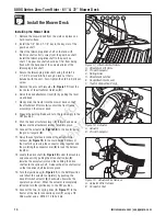
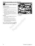
800X Series Zero-Turn Rider - 61” & 72” Mower Deck

ferrismowers.com | snapperpro.com

Figure 32.  Control Handle Pivots & Seat Plate Pivot

A

B

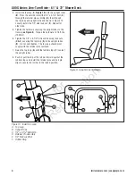
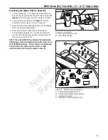
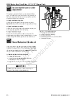
Figure 33.  Idler Arms
A.  PTO Clutch Drive Belt Idler Arm
B.  Hydraulic Pump Drive Belt Idler Arm

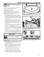
Figure 35.  Attachment Lift Arms & Actuator

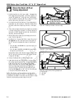
Figure 36.  Deck Lift Rods

Figure 34.  Mower Deck Lubrication Points

Содержание ZTR 800X Series

Страница 1: ...ad understand and follow these warnings and instructions and use safe shop and work practices at all times while working on or around this unit and all other outdoor power equipment TABLE OF CONTENTS...

Страница 2: ...evels Check Engine Oil Level Check Hydraulic Oil Level Check Tire Pressure 8 Check Mower Assembly Check Blade Bolt Torque Check Deck Drive Belt 10 Install the Mower Deck Install the Mower Deck Positio...

Страница 3: ...igure 1 for valve location Figure 2 Disengaging the Parking Brake lever shown in disengaged position A Parking Brake Lever Connect Battery Cables 1 Connect the red positive battery cable B Figure 3 to...

Страница 4: ...in Figure 4 2 Install the ground speed control levers A Figure 4 onto the control lever mount C using the 5 16 18 x 1 bolts 5 16 lock washers and 5 16 flat washers B Prior to tightening the bolts alig...

Страница 5: ...e the Top Loop A Top Loop Tube B Plastic Cap C Rubber Stop A B C Assemble the Top Loop 1 Install the plastic cap B Figure 7 into the end of the top loop tube A Repeat for other end of tube 2 Make sure...

Страница 6: ...ugh the top loop and upright tube and shown in FIgure 10 Loosely install the 1 2 side lock nut E Repeat for other side 5 Tighten the hardware securing the upright tubes to the frame see Figure 8 Torqu...

Страница 7: ...l reservoir A and observe the oil level When cold the oil level should be approximately 4 10 cm below the top of the filler neck 5 If necessary add either Mobil 1 15W 50 synthetic oil or Castrol Synte...

Страница 8: ...NG Avoid injury Mower blades are sharp Mower blades are sharp For your personnal safety do NOT handle mower blades with bare hands Careless or improper handling of blades may result in serious injury...

Страница 9: ...erform the Adjust the Mower Belt Idler Tensioning Spring Length Adjust the Mower Belt Idler Tensioning Spring Length 72 Models Only 1 Loosen the jam nut C Figure 16 on the eye bolt D 2 Turn the adjust...

Страница 10: ...hment lever E forward and down Make sure the attachment latches latch into place 10 Connect the actuator A Figure 18 to the tractor using the pin w lanyard B 11 Raise the seat plate and connect the ac...

Страница 11: ...eight adjustment pin A Figure 21 to the desired cutting height 4 Retract the actuator until contact is made with the cutting height adjustment pin Continue to retract the actuator until the operating...

Страница 12: ...ure 24 To adjust the lift rod loosen the jam nut B Figure 24 on the front clevis C and then remove the 1 2 clevis pin fastening the clevis to the lift pivot arm Turn the clevis CLOCKWISE to cause the...

Страница 13: ...rner of the mower deck with the 3 1 2 sides being vertical See Figure 25 4 Loosen the nuts A Figure 26 and allow the front of the deck to rest on the 2 x 4 s Slide the chains down in the slots until t...

Страница 14: ...e blade from the cutting edge to the ground Measure from the rear tip of the blade from the cutting edge to the ground Repeat the process for the other side of the machine 3 Once the front measurement...

Страница 15: ...rease p n 5022285 is recommended automotive type high temperature lithium grease may be used when this is not available Oil control handle pivots seat plate pivots deck lift pivots discharge chute piv...

Страница 16: ...ferrismowers com snapperpro com Figure 32 Control Handle Pivots Seat Plate Pivot A B Figure 33 Idler Arms A PTO Clutch Drive Belt Idler Arm B Hydraulic Pump Drive Belt Idler Arm Figure 35 Attachment...

Страница 17: ...lve A B Safety Interlock and Mower Deck Positioning Instructions This unit is equipped with an safety interlock system to help keep the operator safe while running the unit Please read and understand...

Страница 18: ...not in the NEUTRAL position OR Test 2 Engine SHOULD crank if PTO switch is NOT engaged AND Parking brake is engaged AND Ground speed control levers are locked in the NEUTRAL position AND Test 3 Engin...

Страница 19: ...suspension and back angle Forward and Backward Adjustment Twist the forward backward seat adjustment lever A Figure 39 counter clockwise position the seat as desired and release the lever to lock the...

Страница 20: ...ver mount bolts D Figure 40 and pivot the lever s C to align with each other To Adjust the Handle Placement Loosen the jam nuts and adjust the placement bolt B in or out to properly adjust the lever e...

Страница 21: ...ust If the machine creeps forward turn the rod CLOCKWISE while standing at the rear of the machine facing forward If the machine creeps backward turn the rod COUNTER CLOCKWISE while standing at the re...

Страница 22: ...on If the levers do not align with the notches in the neutral lock plate it is necessary to adjust the neutral return rod Adjustment 1 Loosen the set collar B Figure 42 locked against the return sprin...

Страница 23: ...ocate the brake spring A Figure 44 4 With the parking brake engaged measure the compressed spring length The spring should be 2 1 4 5 72 cm when compressed 5 If the spring does not measure 2 1 4 5 72...

Страница 24: ...o com Copyright Briggs Stratton Corporation Milwaukee WI USA All rights reserved SNAPPER PRO is a trademark of Briggs Stratton Corporation Milwaukee WI USA FERRIS is a trademark of Briggs Stratton Cor...

Отзывы: