background image

www.snapper.com

Engine Power Rating Information: 

The gross power rating for individual gas engine models is labeled in accordance with SAE

(Society of Automotive Engineers) code J1940 (Small Engine Power & Torque Rating Procedure), and rating performance has
been obtained and corrected in accordance with SAE J1995 (Revision 2002-05). Torque values are derived at 3060 RPM;
horsepower values are derived at 3600 RPM. Actual gross engine power will be lower and is affected by, among other things,
ambient operating conditions and engine-to-engine variability. Given both the wide array of products on which engines are
placed and the variety of environmental issues applicable to operating the equipment, the gas engine will not develop the rated
gross power when used in a given piece of power equipment (actual "on-site" or net horsepower). This difference is due to a
variety of factors including, but not limited to, accessories (air cleaner, exhaust, charging, cooling, carburetor, fuel pump, etc.),
application limitations, ambient operating conditions (temperature, humidity, altitude), and engine-to-engine variability.  Due to
manufacturing and capacity limitations, Briggs & Stratton may substitute an engine of higher rated power for this Series
engine.

Common Service Parts

Part Number

Blade Control Cable 

(All)

7101395

Wheel Drive Cable 

(SP2265FC Only)

7101401

Wheel Drive Cable 

(SPV22675HWFC Only)

7101396

Cutter Blade 

(All)

7100851

Drive Belt 

(SP2265FC Only)

7101193

Drive Belt 

(SPV22675HWFC Only)

7100913

Product Specifications

S2265FC

SP2265FC

SPV22675HWFC

Deck Size 

(in)

22

22

22

Height of Cut 

(in)

1.5 - 3.5

1.5 -3.5

1.5 - 3.5

Transmission Type 

(Self-Propelled Units Only)

N/A

Single Speed/Gear

Variable Speed/Gear

Ground Speed

(mph)

(Self-Propelled Units Only)

N/A

2.3

0 - 4.2

Engine Power 

(ft lbs)

6.50

6.50

6.75

Engine Displacement 

(cc)

190

190

190

Fuel Tank Capacity 

(qt)

1.6

1.6

1.6

22

Snapper Products
535 Macon Street
McDonough, GA 30253

22” WALK BEHIND 
MOWERS

1-800-317-7833

Содержание S2265FC

Страница 1: ...without notice Actual sustained engine power will likely be lower due to operating limitations and environmental factors Please refer to Engine Power Rating Information for further details Manual No 7...

Страница 2: ...RDS Complete the following information on your Snapper purchase Date of Purchase__________________________________________________________________ Retailer_____________________________________________...

Страница 3: ...ce 12 Engine Tipping 12 Cleaning the Mower Housing 12 Lubrication 12 Adjusting the Height of Cut 12 Removing the Drive Belt 13 Adjusting the Drive Cable 14 Blade Service 15 Removing the Blade 15 Sharp...

Страница 4: ...fuel and oil from machine DO NOT smoke 5 Check the area to be mowed and remove all objects such as toys wire rocks limbs and other objects that could cause injury if thrown by blade or interfere with...

Страница 5: ...g grass bag and or clearing grass Operation Continued From Previous Column 13 DO NOT operate mower without the entire grass catch er or guards in place discharge guard rear guard or other safety devic...

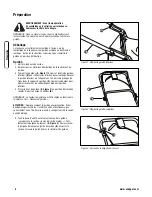
Страница 6: ...three sets of holes in the handle brackets C Turn the knobs to release the locking pins and secure the lower handle 4 Put the upper handle A Figure 2 in the operating upright position Tighten the win...

Страница 7: ...ns Align the lower handle with the desired set of holes in the handle brackets C Turn the knobs to release the locking pins and secure the lower handle Note Do not remove the lower set of bolts and nu...

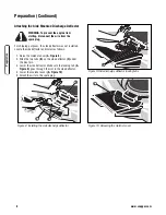
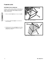
Страница 8: ...side mounted discharge deflector 1 Slide the frame assembly A Figure 5 into the grass bag B 2 Make sure the handle A Figure 6 is on the outside of the grass bag 3 First attach the clips B Figure 6 to...

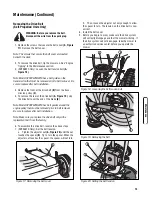
Страница 9: ...rn or damaged replace the parts only with approved factory replacement parts Emptying the Grass Bag WARNING Before you remove the grass bag stop the engine Before you remove any grass from the mower h...

Страница 10: ...aise the mulcher cover A Figure 8 2 Slide the two tabs B on the side deflector C under the pivot pin 3 Lower the side deflector Make sure the locking tab A Figure 9 goes through the slot in the side d...

Страница 11: ...perating limitations and environmental factors Preparation Final Preparation Before you use the mower check the assembly of the wheels the handle and the controls Make sure all the fasteners are tight...

Страница 12: ...e system release the drive lever The drive system will disengage but the engine will continue to run Note When the drive system is disengaged on a new unit it is possible for the front wheels to rotat...

Страница 13: ...ccident make sure the drive lever is in the DISENGAGED position When the drive lever is in the ENGAGED position do not start the engine 5 The primer button A Figure 13 is on the side of the engine Pus...

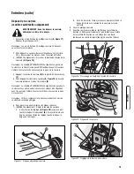
Страница 14: ...park plug Grass and other debris can keep the mower from working correctly After you mow clean the mower housing as follows 1 Stop the engine 2 Disconnect the wire from the spark plug 3 Clean dirt and...

Страница 15: ...es around the engine pulley that must be removed prior to belt removal Be sure to replace after belt installation Note Make sure you replace the drive belt only with a replacement belt from the factor...

Страница 16: ...stop lever several times Make sure the engine stop cable moves freely Note The engine design does not include a throttle control or an engine speed adjustment The engine is set at the best speed for...

Страница 17: ...use an accident 7 Fasten the blade with the original washer D and bolt Make sure the outside rim of the Belleville washer is toward the blade 8 Tighten the bolt that holds the blade to a torque of 30...

Страница 18: ...ull the recoil start grip so that the oil will protect the cylinder Install a new spark plug in the cylinder 5 Clean the dirt and debris from the cylinder cooling fins and the engine housing 6 Clean t...

Страница 19: ...d other debris 3 Check the wire to the spark plug Make sure the wire is connected 4 Clean the engine cooling fins of grass and other debris 5 Check the carburetor adjustments Refer to the engine manua...

Страница 20: ...r from the original purchase date SNAPPER will not be responsible for any installation cost incurred The battery warranty only covers original equipment batteries and does not cover damage to the batt...

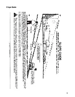
Страница 21: ...19 Slope Guide...

Страница 22: ...www snapper com 20 Notes...

Страница 23: ...21 Notes...

Страница 24: ...factors including but not limited to accessories air cleaner exhaust charging cooling carburetor fuel pump etc application limitations ambient operating conditions temperature humidity altitude and e...

Страница 25: ...avis La puissance continue r elle du moteur est susceptible d tre inf rieure en raison de limites d exploitation et de facteurs environnementaux Pour plus de d tails voir Information sur la puissance...

Страница 26: ...ez les renseignements suivants concernant l achat de votre produit Snapper Date d achat______________________________________________________________________ Revendeur_________________________________...

Страница 27: ...de tondeuse 12 Lubrification 12 R glage de la hauteur de coupe 12 D pose de la courroie 13 R glage du c ble d avance 14 Entretien de la lame 15 D pose de la lame 15 Aff tage de la lame 15 Contr le du...

Страница 28: ...ext rieur uniquement avec le moteur arr t et froid Nettoyer l essence et l huile renvers s sur la machine NE PAS fumer 5 Contr ler la zone tondre et enlever tous les objets tels que jouets c bles pier...

Страница 29: ...plet ni sans la protection d jection la protection arri re ou autres dispositifs de s curit en place et en bon tat de marche NE PAS diriger l jection vers des personnes voitures fen tres ou portes Fon...

Страница 30: ...s groupes de trous dans le support de guidon C Tourner les boutons pour lib rer les broches de verrouillage et bloquer le guidon inf rieur 4 Placer le haut du guidon A Figure 2 en position d utilisati...

Страница 31: ...Aligner le guidon inf rieur sur le groupe de trous souhait des supports de guidon C Tourner les boutons pour lib rer les broches de verrouillage et bloquer le guidon inf rieur Remarque Ne pas d poser...

Страница 32: ...r le d flecteur d jection lat ral 1 Enfiler l armature A Figure 5 dans le sac de ramassage B 2 S assurer que la poign e A Figure 6 est sur l ext rieur du sac de ramassage 3 Encliqueter d abord les bar...

Страница 33: ...us ou endommag remplacer les pi ces exclusivement par des pi ces de rechange homologu es par le fabricant Vider le sac de ramassage AVERTISSEMENT Avant de d crocher le sac de ramassage arr ter le mot...

Страница 34: ...de d chiquetage A Figure 8 2 Enfiler les deux pattes B du d flecteur lat ral C sous la broche pivot 3 Abaisser le d flecteur lat ral V rifier que les pattes de blocage A Figure 9 traversent les rainur...

Страница 35: ...imites d exploitation et de facteurs environnementaux Pr paration Pr paration finale Avant d utiliser la tondeuse contr ler l assemblage des roues du guidon et des commandes V rifier que toute la viss...

Страница 36: ...4 Pour d brayer le syst me de traction seulement rel cher le levier d avance Le syst me de traction se d braye mais le moteur continue de tourner Remarque Sur une machine neuve lorsque le syst me de t...

Страница 37: ...viter les accidents v rifier que le levier d avance est en position D BRAY E Si le levier d avance est en position EMBRAY E ne pas d marrer le moteur 5 Le bouton d amor age A Figure 13 se trouve sur...

Страница 38: ...erbe et autres d bris peuvent emp cher la tondeuse de fonctionner correctement Apr s avoir tondu nettoyer le carter de tondeuse de la mani re suivante 1 Arr ter le moteur 2 D brancher le c ble de la b...

Страница 39: ...t des guides de courroie autour de la poulie du moteur qui doivent tre d pos es avant la courroie Veiller bien les remettre en place apr s la pose de la courroie Remarque Veiller remplacer la courroie...

Страница 40: ...eur actionner plusieurs fois la barre d arr t du moteur V rifier que le c ble d arr t du moteur s actionne librement Remarque Le moteur n est pas quip d une commande des gaz ni d un r glage du r gime...

Страница 41: ...t et peut provoquer un accident 7 Serrer la lame avec la rondelle D et le boulon d origine S assurer que le bord ext rieur de la rondelle Belleville est contre la lame 8 Serrer le boulon de fixation d...

Страница 42: ...ntement la poign e du lanceur pour r pandre l huile et prot ger le cylindre Poser une bougie neuve sur le cylindre 5 Nettoyer la salet et les d bris des ailettes de refroidissement du cylindre et du c...

Страница 43: ...ougie V rifier qu il est branch 4 Nettoyer l herbe et autres d bris des ailettes de refroidissement du moteur 5 Contr ler les r glages du carburateur Consulter le manuel du moteur 6 Contr ler l cartem...

Страница 44: ...pas responsable des frais de pose engag s La garantie de la batterie couvre uniquement les batteries d origine et ne couvre pas les dommages de la batterie ou de la machine caus s par n gligence ou e...

Страница 45: ...tain utiliser ce guide et ne pas tondre une pente sup rieure 15 degr s Si la tondeuse autoport e est utilis e avec un accessoire tract ou fix l arri re ne pas conduire l unit sur une pente ayant une p...

Страница 46: ...www snapper com 20 Notes...

Страница 47: ...21 Notes...

Страница 48: ...dissement carburateur pompe essence etc limites des applications conditions ambiantes d exploitation temp rature humidit altitude et variabilit d un moteur l autre Pour des raisons de limites de fabri...

Страница 49: ...EL WALK BEHIND MOWERS Revision IR TP 400 5394 IR WB N 4 11 2008 Briggs Stratton Yard Power Products Group Manual No 7102508 535 Macon Road McDonough GA 30253 U S A 800 935 2967 MODEL NSPV22675HW 78002...

Страница 50: ...00 5394 IR WB N 22 VARIABLE SPEED HIGH WHEEL 3 Manual No 7102508 PAGE GROUP 4 Handles and Controls SPV22 6 Deck Assembly SPV22 10 Engine and Blade Assembly SPV22 12 Height of Cut Assemblies 14 Transmi...

Страница 51: ...TP 400 5394 IR WB N Manual No 7102508 22 VARIABLE SPEED HIGH WHEEL 4...

Страница 52: ...7300649BH 2 HANDLE Connecting 21 22 WBM 9 7101410 1 ROPE GUIDE 1 4 20 thread 10 7035744 2 KNOB 5 16 18 Wing Black 11 7091189 2 BOLT 5 16 18 x 2 Curved Head Square Neck GR 2 12 7024649 3 WIRE TIE 11 I...

Страница 53: ...Deck Assembly SPV22 TP 400 5394 IR WB N Manual No 7102508 22 VARIABLE SPEED HIGH WHEEL 6...

Страница 54: ...e BB Snapper Cool Gray incl two 1 1 8 O D Flanged Ball Bearings p n 7101380 19 7500542 2 ASSY Drive Wheel 8 x 2 BB Snapper Charcoal Gray incl two 1 1 8 O D Flanged Ball Bearings p n 7101380 20 722604...

Страница 55: ...Deck Assembly SPV22 TP 400 5394 IR WB N Manual No 7102508 22 VARIABLE SPEED HIGH WHEEL 8...

Страница 56: ...k Assembly SPV22 Footnotes TP 400 5394 IR WB N Manual No 7102508 22 VARIABLE SPEED HIGH WHEEL 9 Part No Description Item Qty Note 38 7300440D 1 BAFFLE Front 22 WBM Note See Height of Cut Assemblies pa...

Страница 57: ...Engine and Blade Assembly SPV22 TP 400 5394 IR WB N Manual No 7102508 22 VARIABLE SPEED HIGH WHEEL 10...

Страница 58: ...448 3 7300400D 1 DECK 22 Walk 3 N 1 4 7101195 1 COVER Front Deck 22 FWD 5 7900018 2 SCREW 4 8 x 1 59 x 13mm Hi Lo Round Washer Head Torx 6 7101302 2 SPACER Belt Guide 22 VS 7 7101024 2 BELT GUIDE Engi...

Страница 59: ...Height of Cut Assemblies TP 400 5394 IR WB N Manual No 7102508 22 VARIABLE SPEED HIGH WHEEL 12...

Страница 60: ...47 2 WASHER 391 x 1 x 14 Gage Flat 7 7900046 2 WASHER 76 x 1 25 x 180 Flat 8 7101205 2 LEVER HOC 22 WBM 9 7500409 1 ASSY Rear Axle RH 22 WBM 10 7500408 1 ASSY Rear Axle LH 22 WBM 11 722611 4 WASHER 1...

Страница 61: ...Transmission 22 TP 400 5394 IR WB N Manual No 7102508 22 VARIABLE SPEED HIGH WHEEL 14...

Страница 62: ...art No Description Item Qty Note 1 7100857 1 TRANSMISSION Rocker 22 WBM HW VS 2 7900032 8 SCREW 7mm x 1 x 550 AB Point 3 7100913 1 BELT Traction Drive 22 Pivot Handle 3L Section 31 94 effective length...

Страница 63: ...Decals 22 TP 400 5394 IR WB N Manual No 7102508 22 VARIABLE SPEED HIGH WHEEL 16...

Страница 64: ...r 3 7102151 1 DECAL Briggs Engine 675 Series 3 7102172 1 DECAL Engine TP 675 Snapper FC not shown similar in appearance to 7102151 4 7013010 1 DECAL Danger Cut Finger 5 7102286 1 DECAL CPSC Blade 6 71...

Страница 65: ......

Страница 66: ...MAKE CHANGES OR ADD IMPROVEMENTS AT ANY TIME WITHOUT INCURRING ANY OBLIGATION TO MAKE SUCH CHANGES ON PRODUCTS WALK BEHIND MOWERS Revision IR TP 400 5394 IR WB N 4 11 2008 Manual No 7102508 Copyright...

Страница 67: ...writing from Briggs Stratton Corporation PRINTED IN U S A FORM MS 4257 04 15 2008 FILE IN SECT 2 OF SERVICE MANUAL 126T02 0177 B1 Illustrated Parts List Model Series 126T02 TYPE NUMBER 0177 B1 TABLE O...

Страница 68: ...1 33 36 40 22 20 15 12 4 847 523 287 524 525 842 9 883 1095 VALVE GASKET SET 7 45 34 35 40 45 12 9 7 3 358 ENGINE GASKET SET 883 842 617 524 163 20 585 668 32 32A 27 26 27 25 29 28 24 741 16 43 46 870...

Страница 69: ...in frames 04 15 2008 2 365 601 187 190 972 1059 134 121 CARBURETOR OVERHAUL KIT 104 127 137 163 633 617 276 443 445 968 425 163 11A 966 613 81 883 300 957 291 AUTOCHOKE SYSTEM 97 975 133 134 617 130...

Страница 70: ...4257 3 Assemblies include all parts shown in frames 04 15 2008 3 202 188 334 356 621 851 362 333 209 60 58 592 65 597 456 689 459 1210 1211 55 608 363 23 455 332 305 304 78 37 1036 EMISSIONS LABEL 22...

Страница 71: ...Standard 118 695042 Jet Main High Altitude 121 498260 Kit Carburetor Overhaul 125 794304 Carburetor AutoChoke System 127 D694468 Plug Welch 130 696564 Valve Throttle 133 398187 Float Carburetor 134 D3...

Страница 72: ...690380 Seat Valve Exhaust 871 262001 Bushing Valve Guide Exhaust Note 63709 Bushing Valve Guide Intake 883 K 691881 Gasket Exhaust 922 692135 Spring Brake 923 695891 Brake 957 692046 Cap Fuel Tank Bl...

Страница 73: ......

Страница 74: ......

Отзывы: