www.snapper.com
10
Operation
Engine Stop Lever
Release the engine stop lever
(A, Figure 11)
and the engine
and the blade will automatically stop. To run the engine, hold
the engine stop lever in the Operating position
(B)
.
Before you start the engine, operate the engine stop lever
several times. Make sure the cable moves easily.
Front Wheel Drive System
(Self-Propelled Units Only)
The mower has a front wheel drive system. Operate the drive
system as follows.
1. Hold the engine stop lever
(A, Figure 11)
in the
Operating Position
(B)
.
2.
Model SP2265FC:
Pull the drive lever
(A, Figure 12)
completely back. The drive system is now engaged.
Model SPV22675HWFC:
Slowly pull the drive lever
back. The drive system is now engaged. To increase
ground speed, slowly pull the drive lever farther back.
To decrease ground speed, slowly release the drive
lever.
3. To disengage the drive system and stop the engine,
completely release the engine stop lever.
4. To disengage only the drive system, release the drive
lever. The drive system will disengage but the engine
will continue to run.
Note: When the drive system is disengaged on a new unit, it
is possible for the front wheels to rotate if lifted off the
ground. This is normal and will stop after one or two hours
of operation.
WARNING: For safe operation, the drive
system must immediately disengage when the
drive lever is released. If the drive system
does not disengage correctly, do not operate
the mower until the drive system is adjusted
or repaired by an authorized service center.
Stopping the Engine
To stop the engine, release the engine stop lever. Disconnect
the wire from the spark plug to prevent the engine from
starting.
If the engine will not stop, hold a screwdriver against the
spark plug and against the engine cooling fins. The spark will
go to ground and the engine will stop. Before you start the
engine, check the engine stop cable. Make sure the engine
stop cable is assembled correctly. Before you operate the
unit, replace a bent or damaged engine stop cable.
Figure 11: Operating the engine stop lever
Figure 12: Operating the front wheel drive system
A
B
A
Operation
Содержание S2265FC
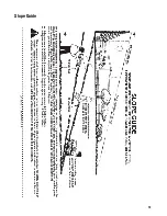
Страница 21: ...19 Slope Guide...
Страница 22: ...www snapper com 20 Notes...
Страница 23: ...21 Notes...
Страница 46: ...www snapper com 20 Notes...
Страница 47: ...21 Notes...
Страница 51: ...TP 400 5394 IR WB N Manual No 7102508 22 VARIABLE SPEED HIGH WHEEL 4...
Страница 53: ...Deck Assembly SPV22 TP 400 5394 IR WB N Manual No 7102508 22 VARIABLE SPEED HIGH WHEEL 6...
Страница 55: ...Deck Assembly SPV22 TP 400 5394 IR WB N Manual No 7102508 22 VARIABLE SPEED HIGH WHEEL 8...
Страница 57: ...Engine and Blade Assembly SPV22 TP 400 5394 IR WB N Manual No 7102508 22 VARIABLE SPEED HIGH WHEEL 10...
Страница 59: ...Height of Cut Assemblies TP 400 5394 IR WB N Manual No 7102508 22 VARIABLE SPEED HIGH WHEEL 12...
Страница 61: ...Transmission 22 TP 400 5394 IR WB N Manual No 7102508 22 VARIABLE SPEED HIGH WHEEL 14...
Страница 63: ...Decals 22 TP 400 5394 IR WB N Manual No 7102508 22 VARIABLE SPEED HIGH WHEEL 16...
Страница 65: ......
Страница 73: ......
Страница 74: ......

