


15
Section 4 - MAINTENANCE
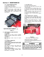
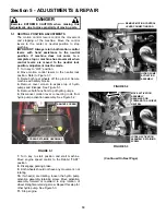
4.2.3. CHECK MOWER DRIVE BELT
1.
Lower deck to lowest setting.
2.
Remove footrest. See Figure 4.3.
3.
Removal of footrest will allow access to mower
drive belt.
4.
Check the belt tension. If belt is frayed, slit,
severed or belt strands exposed, replace belt
before operating mower. Refer to Section
“MOWER DRIVE BELT REPLACEMENT AND
ADJUSTMENT”.
FIGURE 4.3
4.3 AFTER EVERY 25 OPERATING HOURS
4.3.1. ENGINE
1. Engine Oil
Change engine oil. Refer to Section “CHANGE
ENGINE OIL”. Refer to engine owner’s manual for
oil specifications.
2. Air Filter
Refer to engine owner’s manual for service
instructions.
4.3.2. MOWER COMPONENTS
1. Mower Drive Belt
Check belt tension. Replace belt as needed. Refer
to Section “MOWER DRIVE BELT REPLACEMENT
AND ADJUSTMENT”.
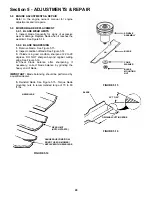
2. Mower Blade
Check blade for sharpness, wear, damage, and
torque. Refer to Section “MOWER BLADE
REPLACEMENT”.
3. Mower Deck Levelness
Check mower deck for proper levelness. Adjust as
required. Refer to Section “MOWER DECK
ADJUSTMENT – LEVELNESS”.
4. Clean Mower Deck
a.
Remove key from ignition switch.
b.
Remove spark plug wire(s) and secure away
from spark plug(s).
c.
Raise mower deck to its highest setting. It may
be necessary to raise mower deck higher using a
hydraulic floor jack. Secure machine with safety
blocks.
d.
Clean underside of mower deck, removing all
accumulation of grass clippings and debris.
e.
Clean top of deck, removing all grass clippings
and debris.
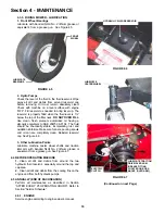
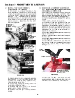
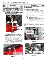
5. Mower Blade Spindle - Lubrication
a.
Raise mower deck to its highest setting. It may
be necessary to raise mower deck higher using a
hydraulic floor jack. Secure machine with safety
blocks.
b.
Lubricate with Kendall NLGI No. 2 lithium
grease or equivalent, from a grease gun. Grease
fittings are located on spindle housings underneath
deck. See Figure 4.4.
FIGURE 4.4
(Deck shown with discharge raised)
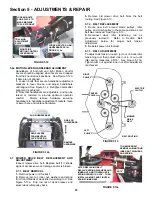
6.
Mower Deck Linkage - Lubrication
Lubricate all mower deck linkage pivot points with a
light coat of motor oil.
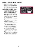
WARNING
DO NOT attempt any maintenance, adjustments or
service with engine running. STOP engine. STOP
blades. Set brake. Remove key. Remove spark plug
wires and secure away from spark plugs. Engine
and components are HOT. Avoid serious burns,
allow sufficient time for all parts to cool.
LUBRICATE
SPINDLE
ASSEMBLIES
LIFT FOOT REST UP AND OFF POWER UNIT
FRAME TO GAIN ACCESS TO MOWER BELT
Содержание CZT19480KWV, CZT19481KWV, HZT2
Страница 33: ...33 PRIMARY MAINTENANCE...
Страница 34: ...34 PRIMARY MAINTENANCE...
Страница 35: ...35 PRIMARY MAINTENANCE...
Страница 36: ...36 PRIMARY MAINTENANCE...
Страница 38: ...38 NOTES...
Страница 39: ...39 NOTES...