background image


10

Section 3 - OPERATING INSTRUCTIONS 

 
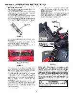
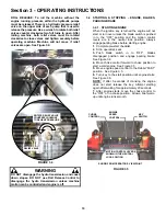
ROLL RELEASE: To roll the machine without the 
engine running, pressure within the hydraulic pumps 
must be released. There is a hydraulic pressure relief 
valve on the upper side of each pump that is used to 
release the pressure. Use a wrench to rotate both relief 
valves counter clockwise two full turns to open. After 
rolling machine, both relief valves must be rotated 
clockwise to close valves and tighten securely before 
operating machine. Machine will not move if relief 
valves are open. See Figure 3.4. 


FIGURE 3.4 


WARNING 

DO NOT disengage the hydro transmission and coast 
down slopes. DO NOT use Roll Release Control to 
disengage the hydro transmission unless machine 
motion can be controlled and engine is off. 


3.2  STARTING & STOPPING – ENGINE, BLADES, 

PARKING BRAKE 
 
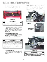
3.2.1. STARTING ENGINE 

When the ignition key is turned the engine will not 
start or turn over unless the blade switch is pushed 
in to the “OFF” position and the motion control 
levers are in the neutral lock position. Always 
engage parking brake before starting engine. 

1. 

Complete pre-start checklist. 

2. 

Sit in operator’s seat. 

3. 

Push blade switch in to “OFF”, blades 

disengaged position and engage parking brake.  
See Figure 3.2. 

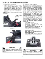
4. 

Move choke control forward to choke position to 

start a cold engine.  See Figure 3.5. 

5. 

Move engine speed control to the Rabbit “FAST” 

position.  See Figure 3.5. 

6. 

Turn key to the start position until engine starts.  

See Figure 3.6. 

NOTE: 

If after 5 seconds of cranking the engine 

does not start, release the key. Attempt starting 
again after waiting for approximately 20 seconds. 

7. 

After engine starts, move the choke control to 

the “OFF” or no choke position.  Allow a brief warm-
up until engine runs smooth. 


FIGURE 3.5 


CHOKE 
CONTROL 

ENGINE 
SPEED 
CONTROL 

KEY 
SWITCH 

SHOWN FROM OPERATOR’S VIEW POINT 

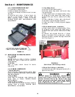
ROTATE RELIEF VALVE 
COUNTERCLOCKWISE 
TO RELIEVE PRESSURE 

RELIEF VALVE 

MOTION CONTROL LEVERS 
SHOWN IN THE NEUTRAL 
LOCK POSITION 

Содержание CZT19480KWV, CZT19481KWV, HZT2

Страница 1: ...Thank you for buying a SNAPPER Product Before operating your machine read this manual carefully and pay particular attention to the IMPORTANT SAFETY INSTRUCTIONS on Pages 2 4 Remember that all power e...

Страница 2: ...rcise EXTREME CAUTION on slopes above 10 degrees 18 grade Turn blades OFF when traveling uphill Use a slow speed and avoid sudden or sharp turns 3 DO NOT operate machine back and forth across face of...

Страница 3: ...use a nozzle lock open device 10 If fuel is spilled on clothing change clothing immediately 11 Never overfill a fuel tank Replace fuel cap and tighten securely OPERATION 1 Mount and dismount machine...

Страница 4: ...tilation when running engine Exhaust gases contain carbon monoxide an odorless and deadly poison 7 Disconnect negative black cable from battery before performing maintenance or service Cranking engine...

Страница 5: ...Fluid Filters 18 SECTION 5 ADJUSTMENTS AND REPAIR 19 27 Neutral Position Adjustments 19 20 Mower Deck Adjustment Levelness 20 21 Parking Brake Adjustment 21 Traction Belt Tension Replacement 22 Blade...

Страница 6: ...s recommended that all operators of this equipment become thoroughly familiar with the controls components and operation of this machine before operating Specific details involving the engine are foun...

Страница 7: ...SYMBOLS DANGER ROTATING PARTS KEEP AWAY FROM MOVING PARTS MOTION CONTROL LEVER OPERATION PARKING BRAKE LEVER OPERATION WARNING AVOID SERIOUS INJURY OR DEATH WEAR HEARING PROTECTION WARNING GUARD OR G...

Страница 8: ...OUT OF MOWING AREA DANGER ROTATING BLADES KEYSWITCH HOUR METER PULL SWITCH UP TO ENGAGE BLADES PUSH SWITCH DOWN TO DISENGAGE BLADES CHOKE CONTROL ENGINE SPEED CONTROL CONTROL PANEL IDENTIFICATION FAS...

Страница 9: ...Make sure both fuel filler caps are tight Note the fuel tank selector valve behind left side of operator s seat Refer to engine owner s manual for fuel specifications 3 1 7 Adjust position of operato...

Страница 10: ...ll not start or turn over unless the blade switch is pushed in to the OFF position and the motion control levers are in the neutral lock position Always engage parking brake before starting engine 1 C...

Страница 11: ...nds If the blades continue to rotate after 5 seconds the electric clutch should be checked Adjustment or replacement of electric clutch may be necessary Return the machine to an authorized Snapper dea...

Страница 12: ...usly variable from neutral zero to the maximum Moving the levers farther from the neutral position will cause the speed of motion to increase To turn move the lever on the side to which you want to tu...

Страница 13: ...ce is not in place and functioning properly DO NOT attempt to defeat modify or remove any safety device ENGINE MUST NOT START IF 1 Motion Control Lever s are not in the neutral lock position OR 2 Park...

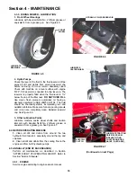
Страница 14: ...pull out to open the drain plug See Figure 4 1 FIGURE 4 1 3 After all the oil has drained close the drain by pushing in and rotating clockwise to close Wipe up any oil that may have spilled Dispose of...

Страница 15: ...emove spark plug wire s and secure away from spark plug s c Raise mower deck to its highest setting It may be necessary to raise mower deck higher using a hydraulic floor jack Secure machine with safe...

Страница 16: ...ure funnels pouring spouts and oil can are completely clean Reinstall reservoir cap See Figure 4 6 3 Other Lubrication Points Lubricate machine caster wheel shafts and traction idler arm with Kendall...

Страница 17: ...ow direction Reinstall fuel line clamps See Figure 4 8 FIGURE 4 8 4 6 DECK REMOVAL Move power unit mower deck to an area where the mower deck is to be disconnected Turn engine OFF and remove key from...

Страница 18: ...ocks from underneath deck and roll slide deck from underneath power unit 9 Reinstall deck in reverse order in which it was removed Torque hardware to 20 to 30 ft lbs 4 7 HYDRAULIC FLUID FILTER IMPORTA...

Страница 19: ...blocks 4 Remove cover screen to expose top of hydro pumps and linkages See Figure 5 1 5 Remove both fans from top of hydro pumps 6 Disconnect motion lever connecting rods from hydro pump activation as...

Страница 20: ...deck will be level side to side within 1 8 have a low cut setting of approximately 1 and the blades pitched approximately 3 16 higher at the rear 1 Place machine on a smooth level surface 2 Check sid...

Страница 21: ...Adjust up or down as required FIGURE 5 7 WARNING Do not operate this machine if the brakes are not functioning properly 5 3 PARKING BRAKE ADJUSTMENT The parking brake can be adjusted to increase brake...

Страница 22: ...isengages the electric clutch when the blade switch is pushed in to the OFF position When the blade switch is in the OFF position the cutting blade s are disengaged The electric clutch is adjustable T...

Страница 23: ...back 3 Remove old mower drive belt Note the belt routing See Figure 5 13 5 7 2 BELT REPLACEMENT 1 Route new belt around blade pulleys idler pulley and clutch pulley in the same position as old belt wa...

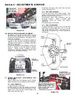
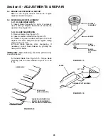
Страница 24: ...blade is in good condition sharpen at 22 to 28 degrees DO NOT sharpen beyond original cutting edge See Figure 5 16 4 Check blade balance after sharpening If necessary correct blade balance by grinding...

Страница 25: ...10 2 BATTERY INSTALLATION 1 Position battery into battery compartment 2 Connect cables to battery terminals Connect RED Positive cable first Connect BLACK Negative cable last See Figure 5 18 3 Reinsta...

Страница 26: ...o service after the date shown charge battery Refer to section BATTERY CHARGING 4 After charging if required slide battery partially into battery housing 5 Connect positive cable red first from wiring...

Страница 27: ...AE 20W50 automotive oil See Figure 4 6 2 Open pressure relief valve on hydraulic pump turning counter clockwise 2 full turns See Figure 3 3 3 Carefully raise the rear of the machine so the wheels are...

Страница 28: ...oke control to OFF position 3 Fuel tank empty 3 Fill with fuel to proper level or switch tanks 4 Engine air pre cleaner and or air cleaner dirty 4 Clean free of all debris 5 Spark plug defective or ga...

Страница 29: ...T position 4 Forward speed too fast 4 Move joystick to a slower speed 5 Terraced cut side to side 5 Adjust side to side level 6 Excessive deck pitch front to rear 6 Adjust front to rear level 7 Cuttin...

Страница 30: ...For Wear Damage Replacement Pages 24 X Mower Deck Clean Debris Accumulation Page 15 X Lubrication Points Grease or Oil Pages 15 16 X X Hydrostatic Trans Oil Check Oil Level Page 16 X X Hydrostatic Tr...

Страница 31: ...om the original purchase date SNAPPER will not be responsible for any installation cost incurred The battery warranty only covers original equipment batteries and does not cover damage to the battery...

Страница 32: ...e original purchase date SNAPPER will not be responsible for any installation cost incurred The battery warranty only covers original equipment batteries and does not cover damage to the battery or ma...

Страница 33: ...33 PRIMARY MAINTENANCE...

Страница 34: ...34 PRIMARY MAINTENANCE...

Страница 35: ...35 PRIMARY MAINTENANCE...

Страница 36: ...36 PRIMARY MAINTENANCE...

Страница 37: ..._______________________ Retailer s Phone Number_________________________________________________ It is very important that you register your purchase with Snapper to ensure warranty coverage Please ma...

Страница 38: ...38 NOTES...

Страница 39: ...39 NOTES...

Страница 40: ...questions about your Snapper product contact your local authorized Snapper dealer or contact Snapper Customer Service at Snapper McDonough GA 30253 Phone 1 800 935 2967 COPYRIGHT 2004 SNAPPER A DIVISI...

Отзывы: