16
|
Quick Start Guide
|
17
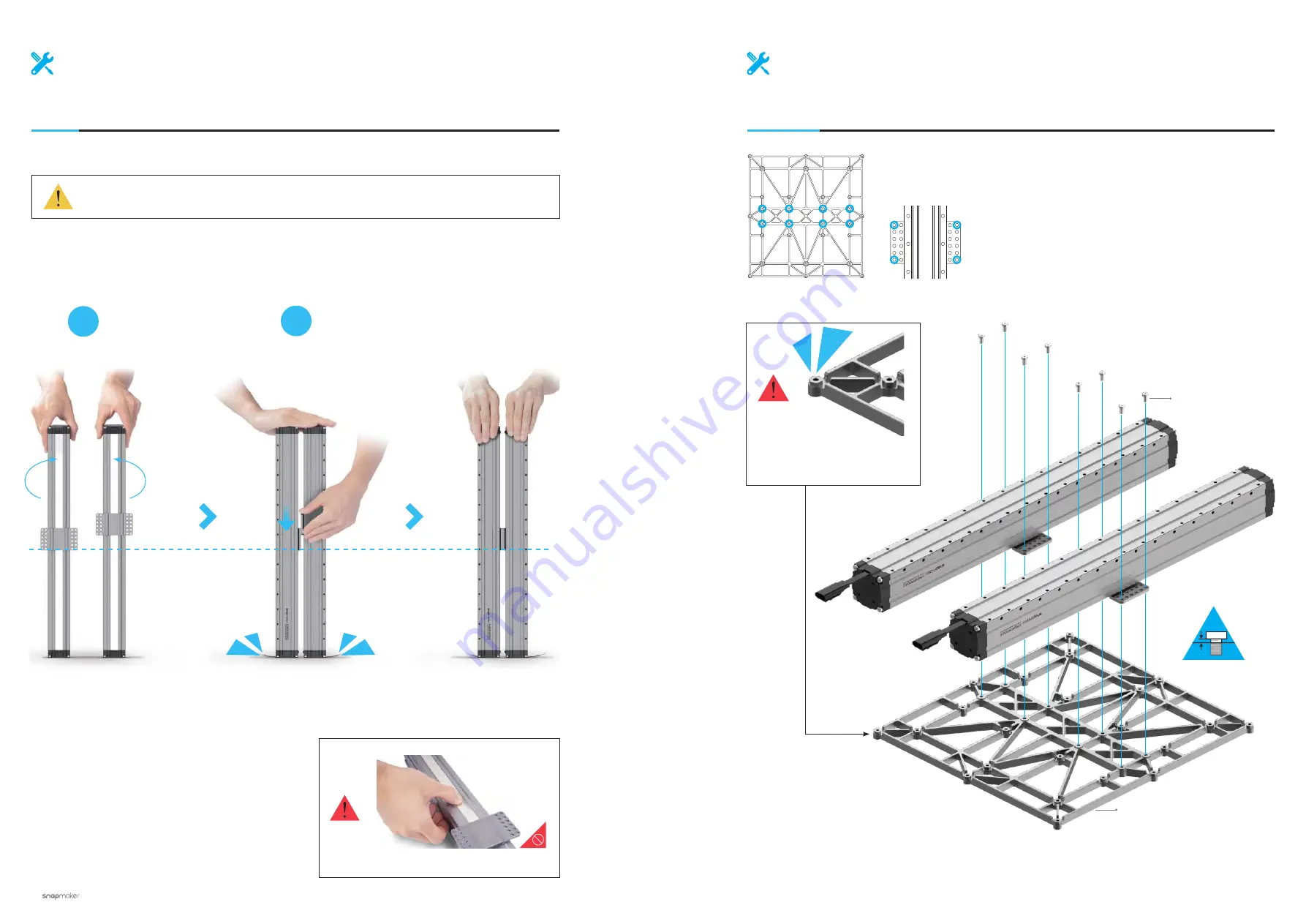
Machine Assembly
M4 x 8 Screw
x 8
04
/24
Attach the Y Axes to the Platform. Do not tighten the screws until Step 6.
Platform
x 1
Make sure to assemble the
Platform in correct orientation.
03
/24
Make sure the sliders are aligning with each other. If not, you can move
them to the same position as illustrated.
DONE!
1
2
Hold the Linear Modules carefully to prevent them from falling.
Do not press the steel strip.
Содержание A350T
Страница 1: ...QUICK START GUIDE MAKE SOMETHING WONDERFUL A350T...
Страница 10: ...12 Quick Start Guide 13 Machine Assembly MACHINE ASSEMBLY...
Страница 51: ...94 CNC Carving...