background image

28 

SMOOTH AGILE TRAINER 


ASSEMBLY 


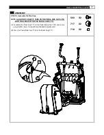
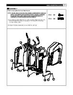
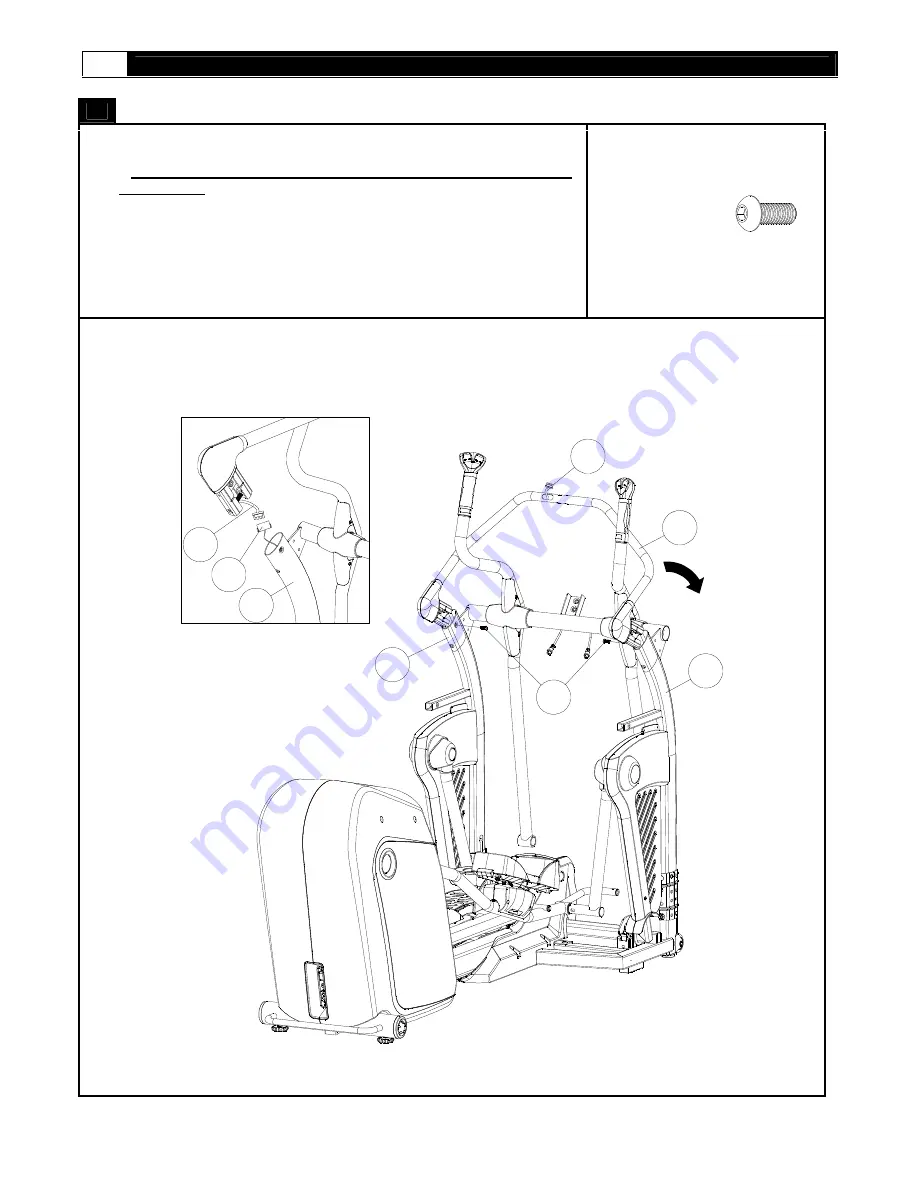
STEP 9: Assemble the Console Support Tube 
 
NOTE: INSERT BOTH ENDS OF THE CONSOLE SUPPORT TUBE AT THE 

 SAME TIME. 


(A) Connect the 8Pin Power Wire-Upper (616) to the 8Pin Power Wire-Middle 
     (617). 
 
(B) Assemble the Consol Support Tube (103) to the Upright and secure using 
     the M8 x 20mm Allen Head Bolt (504). 


504 

X2 


504

110

111

103

616

110

617

616

FIG 1


Содержание AGILE DMT

Страница 1: ...USER S MANUAL SMOOTH AGILE TRAINER USER WEIGHT LIMITATION 350lbs 160kgs SERIAL NUMBER found on frame...

Страница 2: ...have gathered all the necessary tools you may require to assemble the unit properly Having all of the necessary equipment at hand will save time and make the assembly quick and hassle free Clear your...

Страница 3: ...The manufacturer recommends a single outlet surge protector with a UL 1449 rating as a Transient Voltage Surge Suppressor TVSS with a UL suppressed voltage rating of 400V or less and an electrical ra...

Страница 4: ...dentifies the major components you will use to assemble this product Main Frame Assembly Handlebar Assembly BOX A BOX B Base Frame Fixed Handlebar Main Frame Assembly Handlebar Assembly Undercarriage...

Страница 5: ...www smoothfitness com 5 SUPPLIED COMPONENTS This list identifies the major components you will use to assemble this product 712 711 709 710 BOX C BOX D Pivot Arm Cover Computer Front Side Panel...

Страница 6: ...PCS M6 x 40mm Screw 509 2PCS 12 x 20 x 2 Spring Washe r 510 1PCS M10 Nylon Nut 511 10PCS 4 x 12mm Screw 512 6P CS 4 x 19mm Screw 513 2P CS 12 x 18 x 24 5mm Sleeve 514 2PCS 12 x 22 x 2 Washer 515 4PCS...

Страница 7: ...16 117 Clamp Bracket 2 AGILE 117 118 Flywheel 1 AGILE 118 119 Tension Wheel Bracket 1 AGILE 119 120 Pedal Swing Arm 2 AGILE 120 121 Hold Base Front 1 AGILE 121 200 201 Bearing 6004 4 AGILE 201 202 Bea...

Страница 8: ...0 241 3 8 Cable Tie 4 AGILE 241 242 Wheel Bushing 4 AGILE 242 243 Bearing 6000 3 AGILE 243 244 Self adhesive Wire Clip 1 AGILE 244 245 Incline Frame Bushing 1 2 AGILE 245 246 Incline Frame Bushing 2 2...

Страница 9: ...3 Fixing Insert Metal Inside 10 AGILE 333 336 Action Handlebar Front Cover 4 AGILE 336 337 Action Handlebar Cover 2 AGILE 337 338 Elbow Left 2 AGILE 338 339 Elbow Right 2 AGILE 339 342 Fan Bracket Top...

Страница 10: ...ILE 425 426 3 4 Nut 2 AGILE 426 427 Flywheel Axle 1 AGILE 427 428 Shaft 10x36mm 2 AGILE 428 429 Shaft 12x210 M14x70mm 1 AGILE 429 430 Bushing 12x62mm 4 AGILE 430 431 M4x15mm Screw 2 AGILE 431 432 4 x...

Страница 11: ...E 469 470 3x10x1mm Washer 8 AGILE 470 471 6x14 5 M5x6 5mm Bolt 2 AGILE 471 500 501 12x62 M10x20mm Bolt 2 AGILE 501 502 20 x 78 M14x25mm Bolt 2 AGILE 502 503 M5x8mm Screw 2 AGILE 503 504 M8x20mm Allen...

Страница 12: ...ire 1 AGILE 620 621 Hand Pulse Sensor Wire Top 2 AGILE 621 622 Hand Pulse Sensor Wire Upper 2 AGILE 622 623 Hand Pulse Sensor Wire Lower 2 AGILE 623 624 Receiver Wire 1 AGILE 624 625 Fan 1 AGILE 625 6...

Страница 13: ...2 AGILE 718 719 Undercarriage Cover Left 1 AGILE 719 720 Undercarriage Cover Right 1 AGILE 720 721 Pedal Arm Front Pivot Cover 4 AGILE 721 A Screwdriver L 1 AGILE A B 2 5mm Allen Key 1 AGILE B C 5mm A...

Страница 14: ...TS DIAGRAM MOST OF THE PARTS SHOWN HERE HAVE BEEN PRE ASSEMBLED 509 504 102 208 449 101 352 455 627 703 401 312 314 455 350 349 461 351 466 313 355 471 420 353 420 471 464 455 625 342 343 432 208 432...

Страница 15: ...7 462 204 413 331 307 406 309 308 405 450 421 419 207 220 421 404 430 207 233 437 323 459 448 310 323 311 448 106 438 502 460 457 232 330 721 326 107 460 204 437 323 462 417 442 205 207 419 421 413 23...

Страница 16: ...2 431 221 218 226 214 222 414 202 435 426 221 411 441 443 404 216 434 226 210 434 217 405 322 427 436 440 405 405 440 439 442 439 120 511 423 444 717 503 718 503 717 325 211 114 115 325 508 516 243 24...

Страница 17: ...04 605 603 306 333 448 332 304 319 318 448 402 445 119 203 403 409 422 446 231 448 512 719 507 326 326 448 328 461 448 607 454 610 453 324 452 319 448 332 448 305 302 318 601 329 303 450 450 105 104 4...

Страница 18: ...209 448 336 432 336 337 448 416 506 109 111 103 701 721501 702 514 515 721 504 209 504 447 227 225 505 339 338 339 338 225 227 447 113 326 326 513 710 513 512 332 332 713 714 332 709 315 316 317 320 4...

Страница 19: ...s com 19 PARTS DIAGRAM MOST OF THE PARTS SHOWN HERE HAVE BEEN PRE ASSEMBLED 607 609 601 613 619 620 620 614 615 616 617 617 618 619 620 614 620 619 613 613 623 623 623 622 350 624 621 615 625 606 650...

Страница 20: ...nce to position Base Frame 104 for assembly C Position Base Frame 104 under mounting bracket of the Main Frame 105 and align the 4 hole bolt pattern D Remove cardboard block and lower Main Frame 105 o...

Страница 21: ...oles in the Incline Transmission Tube Front 115 C Assemble the Incline Transmission Tube Front 115 to the Base Frame 104 with M10 x 62mm Allen Head Bolt 508 and M10 Nylon Nut 511 by 6mm Allen Key D an...

Страница 22: ...ER WIRE LOWER 618 BE CAREFUL NOT TO DISCONNECT THE WIRE WHEN ASSEMBLING THE UNDERCARRIAGE COVER LEFT 719 A Lift the Pedal Arm and assemble the Undercarriage Cover Left 719 to the Base Frame 104 and se...

Страница 23: ...e Pedal Swing Arm 120 through the hole in the Pivot Arm Cover RL 707 and maneuver the Pivot Arm Cover RL 120 to it s final upright position See the illustrations in STEP1 STEP2 and STEP3 B Repeat the...

Страница 24: ...Do not completely tighten M6 x 12mm Allen Head Bolts until STEP 11 C Align the M8x105x20mm Carriage Bolt 519 with M8x20x1 5mm Cup Washer 517 to thread the Upright and Base Frame and then use the M8 N...

Страница 25: ...6 Assemble the Pivot Arm Covers A Assemble the Pivot Arm Cover RR 706 and the Pivot Arm Cover 707 using the press fit pins and secure to the frame using four 4 x 12mm Screws 512 B Repeat the above pro...

Страница 26: ...Connect the Pedal Arm to the Pedal Swing Arm A Slide the 20 x 78 M14 X 35mm Bolt 502 through the Pedal Arm Right 107 and Pedal Swing Arm 120 the secure by 8mm Allen Key E B Repeat the above procedure...

Страница 27: ...ON THE PEDAL SIDE CAPS 718 WITH THE 3 SNAP FIT ON THE PEDAL CAPS 717 A Assemble the Pivot Cap 717 to the Pedal Swing Arm 120 and secure using the M5 x 8mm Screw 503 by Slotted Screwdriver G B Press t...

Страница 28: ...ERT BOTH ENDS OF THE CONSOLE SUPPORT TUBE AT THE SAME TIME A Connect the 8Pin Power Wire Upper 616 to the 8Pin Power Wire Middle 617 B Assemble the Consol Support Tube 103 to the Upright and secure us...

Страница 29: ...ar 101 to the Console Support Tube 103 and Crossbar 102 B Secure the Fixed Handlebar 101 to the Crossbar 102 with two M8 x 20mm Allen Head Bolts 504 C Secure the Fixed Handlebar 101 to the Console Sup...

Страница 30: ...the M8 x 65mm Allen Head Cap Bolt by 6mm Allen Key D as show in STEP1 B Tighten the M6 x 12mm Allen Head Bolt 520 by 4mm Allen Key L as show in STEP2 C Tighten the M8 Nylon Nut 517 by Wrench F as sho...

Страница 31: ...www smoothfitness com 31 ASSEMBLY STEP 12 Assemble Upright Side Covers A Press the Upright Side Cover Left 701 and Upright Side Cover Right into the Upright sides 701 X1 702 X1 701 110 702 111...

Страница 32: ...Linkage Right 113 and secure using the 12 x 62 M10 x 20mm Bolt 501 12 x 2 x 2mm Spring Washer 510 12 x 22 x 2mm Washer 515 and 12 x 18 x 24 5 Sleeve 514 by 6mm Allen Key D as show in FIG1 B Repeat th...

Страница 33: ...EP 14 Assemble the Pedal Arm Front Pivot Covers A Press the Pedal Arm Front Pivot Cover 721 into the ends of the Action Handlebar Right 109 and Pedal Arm Right 107 B Repeat the above procedure on the...

Страница 34: ...34 SMOOTH AGILE TRAINER ASSEMBLY STEP 15 Tighten Set Screws A Secure the M5 x 6mm Screw 516 to the Pedal Swing Arm 120 using the 2 5mm Allen Key B 516 X2 B 120 106 516 516 B 120...

Страница 35: ...ELS CONNECT TO EACHOTHER USE THESE HOLES AS REFERENCES TO CORRECTLY POSITION THE PLASTIC PANELS A Assemble the Front Side Panel LL 709 and Front Side Panel LR 710 to the left Upright and secure using...

Страница 36: ...TO THE FRAME A Connect the 8Pin Power Wire Top 615 to the 8Pin Power Wire Upper 616 as show in FIG1 B Assemble the Computer 312 to the Console Support Tube 103 and secure using two M6 x 40mm Screws 50...

Страница 37: ...hfitness com 37 ASSEMBLY STEP 18 Assemble Console Back Cover A Assemble the four Taper Fixing Inserts 326 to the Console Back Cover 703 B Assemble the Console Back Cover 703 to the Computer 312 326 X4...

Страница 38: ...the AGILE Dynamic Motion Trainer while adjusting the levelers Tip the AGILE Dynamic Motion Trainer to the left right You will then see the LEVEL ADJUSTERS These will need to be screwed either in or ou...

Страница 39: ...oller controls the Intensity Level You can see the corresponding readouts on the console follow this same orientation To use the Lite Touch Controls simply start a program or select START and begin yo...

Страница 40: ...40 SMOOTH AGILE TRAINER TRANSPORT INSTRUCTION TRANSPORT INSTRUCTIONS To transport your AGILE Dynamic Motion Trainer simply lift the back end and roll it away to the desired location as shown...

Страница 41: ...primarily lower body muscle groups These muscle groups are shown in gray color on the chart below MUSCLE GROUPS A Shoulder muscles Calf muscles G B Pectoral muscles Trapezius muscles H C Bicep muscle...

Страница 42: ...r Thigh Stretch Sit with the soles of your feet together with your knees pointing outward Pull your feet as close into your groin as possible Gently push your knees towards the floor Hold for 15 count...

Страница 43: ...A B C D E F G H I J K L M N MODE A B DTAT DISPLAY 1 INTENSITY LEVEL C D INTENSITY PROFILE FAN CONTROL E F STOP ENTER INTENSITY UP DOWN G H EXPRESS MOTION MOTION UP DOWN I J START VOLUME CONTROL K L MO...

Страница 44: ...Matrix displays and begins showing U1 The other LED windows will show the factory settings as follows INTENSITY LEVEL window display 0 MOTION LEVEL window display 0 DATA DISPLAY 1 displays default AGE...

Страница 45: ...and to set user parameters SET UP USER CODE At first the INTENSITY PROFILE will show a blinking U1 and will also display only factory default setting values for user WEIGHT and AGE Press the INTENSITY...

Страница 46: ...program the TIME display shows L1 This indicates the intensity level for the intervals Use the INTENSITY UP DOWN buttons to change the intensity then press STOP ENTER button to enter to confirm TIME d...

Страница 47: ...ROGRAM After enter this program the TIME display shows L1 Press INTENSITY UP DOWN button to adjust the workout level and press STOP ENTER to confirm TIME display shows factory default setting 32 00 Pr...

Страница 48: ...s a standard contact handgrip on the moving handle bar to sense the user heart beat during the workout The user must hold the contact handgrips on the moving handle bar constantly in order to monitor...

Страница 49: ...ENSITY LEVEL at level 1 and MOTION LEVEL at level 1 C1 C5 CUSTOMER COURSE The program can allow store the settings for repeated workouts After enter this program and press STOP ENTER button the user c...

Страница 50: ...the original product Any technical advice furnished before or after delivery in regard to the use or application of Smooth Fitness products is furnished without charge and on the basis that it repres...

Страница 51: ...www smoothfitness com 51 Smooth Fitness 780 5 th Ave King of Prussia PA 19406 Toll Free Customer Service 1 888 800 1167 Website www smoothfitness com...

Отзывы: