Below the gear formula is a repetition of the
“Do not change selector
handle positions while the machine is running”
symbol.
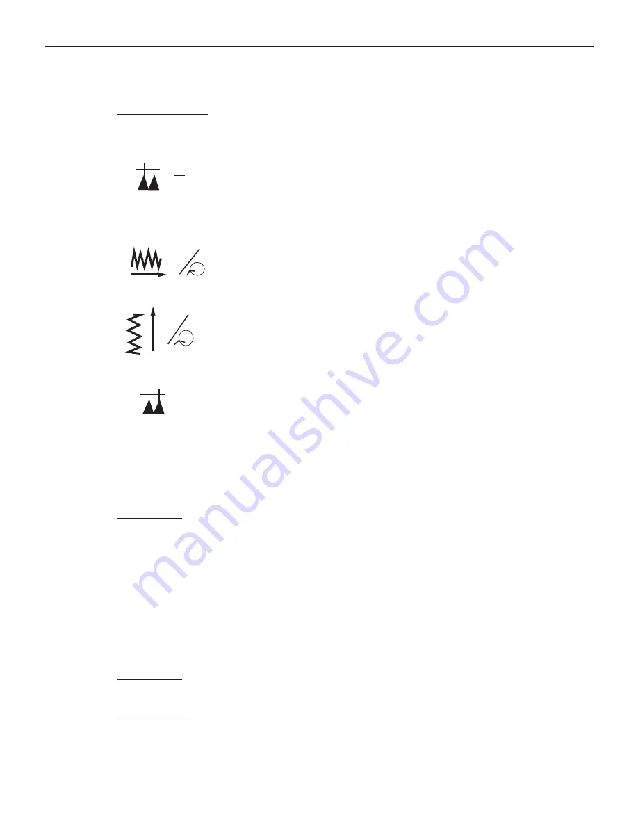
The Header Row contains a number of symbols explained below:
This symbol refers to inch thread pitches (threads per inch).
The “N” represents the distance the carriage assembly
travels for each rotation of the spindle based on the positions
of the selector lever (I-III) and selector lever 1-7. For
example, if the distance traveled in one rotation of the
spindle is 1/10 inch per rotation, the machine will travel 1
inch in 10 rotations, yielding 10 threads per inch (tpi).
This symbol represents the longitudinal (X-Axis Travel) in
inches per spindle revolution.
This symbol represents the lateral Y-Axis Travel) in
inches per spindle revolution.
This symbol refers to the the inch thread pitch. Inch pitches
measures the distance between each thread peak.
Directly below this set of symbols is a row of Roman Numbers I-III, This row
represents the position of the selector lever (I-III) when cutting a threads or
determining a feed rate.
Section one of the chart list the inch thread pitches that can be cut with the
Granite series machines. The last row corresponding with the gear location
guide shows the position of the gears inside the pulley box. When cutting inch
threads the following gears are required:
A=30
B=66
C=60
D=60
This is the default setting from the factory.
Section two of the chart list the feed rates for the X-Axis (longitudinal feed).
The same gear set-up is required as for cutting inch threads.
Section three of the chart list the feed rates for the Y-Axis (lateral feed). The
same gear set-up is required as for cutting inch threads.
1”
N
in
in
in
8: Speeds & Feeds
8-7
Or Visit www.smithy.com


