Page 8
SERIES 28HE STEAM BOILER INSTALLATION AND OPERATION INSTRUCTIONS
2. Carefully place the back section in position on the
angles as shown in Figure 4.
WARNING: The section MUST be fully supported
to prevent it from falling! Failure to comply
with this warning may result property damage,
severe personal injury or death!
Figure 4 - Section Placement
3. Clean the hydronic port connector sealing surfaces
and the rope grooves with a wire brush to remove
any rust or debris.
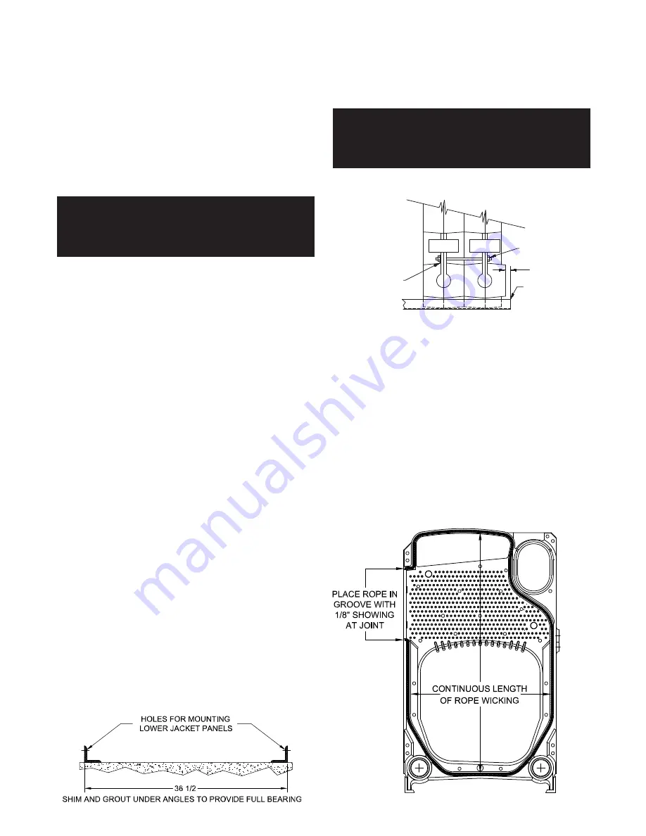
4. Apply two coats of the spray adhesive supplied with
the boiler to the rope groove. Allow time for the fi rst
coat to dry before applying the second coat. When
the second coat is tacky press the rope into the rope
groove. Trim the rope off leaving
1/8 in
.,
3.2 mm
extending beyond the surface of the cast iron
section, Figure 5.
Figure 5 - Rope Installation
Completed boilers must be tested as follows:
Steam Boilers – the assembled boiler sections shall be
subjected to a hydrostatic test pressure of not less than
45 psig
, (
315 kPa
.)
The hydrostatic pressure shall not exceed the required
test pressure by more than
10 psig
, (
70 kPa)
during
the test.
WARNING: Never leak test the boiler using
compressed air! Failure to comply with this
warning may result in property damage, severe
personal injury or death!
1. Plug all openings in the boiler and fi ll it with water.
2. Bleed any air off through one of the top tappings
then increase the pressure as outlined above.
3. Maintain the test pressure while carefully checking
for leaks. If a leak is found it must be eliminated, see
Table 4 and supporting text. Once the assembled
boiler sections pass the hydrostatic test drain them
and remove the plugs from any tappings that will be
used in service.
4. Do not leave boiler unattended while performing
hydrostatic pre-fi re test.
NOTE: The shipping lugs, lifting lugs and metal
banding should be removed before installing the
jacket on factory assembled sections.
CAUTION: Remove the left jacket panels on fully
packaged boilers and ensure that the cleanout
covers are secure and gas tight. Loose covers could
damage the boiler.
Assembly of Knocked-Down Boilers
Drilled and tapped steel angles are furnished to provide
a level footing, ease of section assembly and a point of
jacket attachment.
1. Set the angles as shown in Figure 3. They must be
parallel and level. Grout under the angles to provide
a continuous bearing surface.
Figure 3 - Steel Angle Placement
MIN.- FLUSH
MAX. 3/8
INTER.
SECTION
BACK
SECTION
FLOOR ANGLE
FIXED NUT-NO WASHER
DO NOT TORQUE
WASHER ON SIDE TO BE
TORQUED. USE ANTISIZE
ON THREADS


