


SECTION 3: START-UP & OPERATION
SEQUENCE OF OPERATION
For sequence of operation of the particular boiler being
installed, refer to Figures 2.8, 2.9, 2.10 and 2.11 in Section 2
of this manual.
Spill and rollout switches are mounted on all GB200 boilers.
The spill switch detects the escape of combustion products
through the draft diverter relief opening and interrupts the
power to the gas valve preventing unsafe boiler operation.
Escape of flue products could be caused by a blocked or col-
lapsed chimney or inadequate chimney draft. This is a manu-
al reset-type device and can be reactivated by depressing
the spill switch reset button mounted on the left of the boiler’s
draft diverter (see Figure 2.1 for switch location).
The rollout switch prevents flame rollout from the boiler com-
bustion chamber, caused by blocked boiler flue passage-
ways, by interrupting power to the gas valve to prevent
unsafe boiler operation. This is a manual reset-type device
and can be reactivated by depressing the rollout switch reset
button mounted on the lower front jacket panel (see Figure
2.1 for switch location). Flue passages must be inspected by
a qualified installer if this problem occurs, prior to switch
replacement.
PRIOR TO START-UP
Fill system with water until the water level indicator (sight
glass) is approximately 2/3 full. This water level is 23" from
the surface on which the boiler sits.
SYSTEM START-UP & ADJUSTMENTS
Safe lighting and other performance criteria were met with
the gas manifold and control assembly provided on the boiler
when the boiler underwent tests specified in ANSI Z21.13-
LATEST EDITION
1. Check combination gas valve on boiler and make sure it
is in the OFF position.
2. For vent damper-equipped models, with the thermostat
set to call for heat, observe that vent damper position
indicator rotates to the open position (see Figure 2.5).
Damper must be in the open position when appliance
main burner is operating.
a. After damper opens, spark should appear at the pilot
ignition electrodes.
b. Set thermostat to no longer call for heat. Spark should
stop. Observe that damper position indicator rotates to
the closed position.
c. Set thermostat to call for heat.
3. Light the boiler. For Model GB200 boilers with intermit-
tent pilot, see lighting instruction on Page 14.
4. Observe pilot and main burner flame (see Figure 3.2).
All burner ports should be ignited and burn with a steady
blue flame.
CAUTION: Never leave the job with yellow burning
flames. This condition indicated poor combustion and
will quickly carbonize the boiler, reducing efficiency and
boiler life. It may also be an indication of improper vent-
ing or combustion air supply. If unable to adjust flame
properly, consult your local utility.
5. Boilers are shipped from the factory with the primary air
shutters on the main burner wide open. It is recommend-
ed these air shutters be left in the wide open position
unless there is lifting of the flame above the burner ports.
If there is lifting, the air shutters should be gradually
closed until the lifting is eliminated. It may also be neces-
sary to adjust the primary air shutters if the input rate is
reduced by a change in the orifices.
6. After burner has been in operation for about 10 minutes,
check gas input rate to boiler as follows:
a. Make sure all appliances served by the meter are
turned off during timing of gas input rate to the boiler.
b. Measure the time in seconds that it takes for the boiler
to use 10 cubic feet of gas. Divide 36,000 by the number
of seconds (this is the number of cubic feet of gas used
per hour). Multiply this figure by the heating value of the
gas to obtain Btu input per hour.
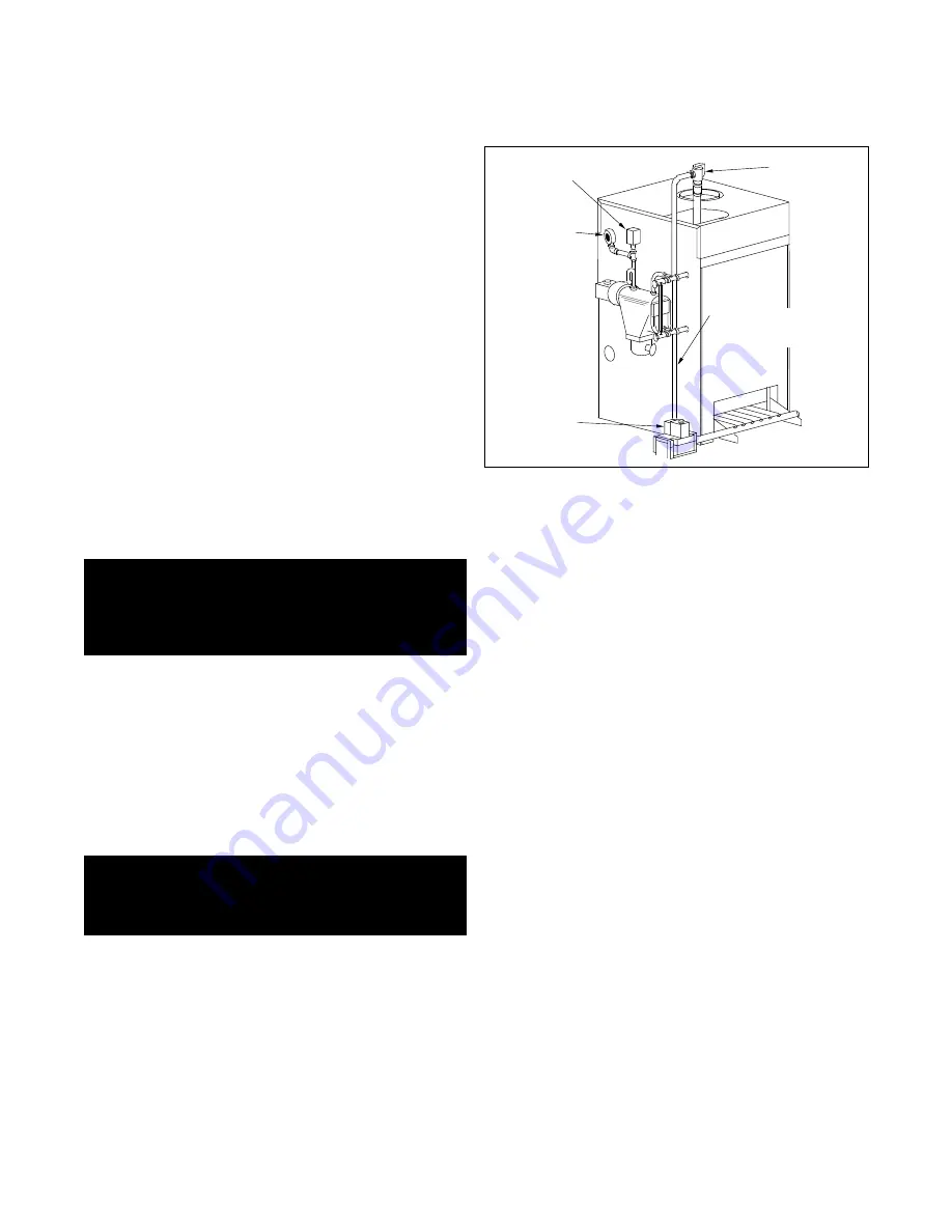
FIGURE 3.1: STEAM CONTROL ARRANGEMENT
WARNING: If boiler cannot be restored to normal
operation after re-setting of spill switch, or if flame
rollout switch has tripped, do not attempt to put the
boiler in operation. Immediately contact a qualified
service professional.
WARNING: Keep boiler area clear and free from com-
bustible materials, gasoline and other flammable
vapors and liquids. Otherwise fire or explosion may
result.
PRESSURE
RELIEF VALVE
OPTIONAL
FLOAT
LOW WATER
CUT OFF
PRESSURE
CONTROL
PRESSURE
GAUGE
GAS VALVE
PRESSURE RELIEF
VALVE DISCHARGE
PIPING
11
Содержание GB200 SERIES
Страница 19: ...19...