background image

COSMOS 302X series servo drives / inverters

Installation, use and maintenance manual - EN

Ver. 1.01

27 

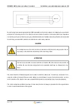
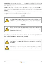
5.3.3    Auxiliary power supply and 24V digital inputs

The drive is equipped with a connector for connecting the 24V auxiliary power supply and the digital inputs.

The pinout of the connector provided for this purpose is shown in the following paragraphs.

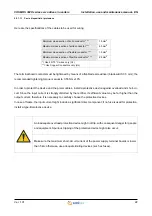
The servo-drive uses a detachable connector with spring connection, the acceptable sections of the cables to

be used for wiring are the following:

Use a flat-head screwdriver to wire the connector; insert the edge of the head into the orange cavity and press

to open the contact. At the same time, insert the cable. It is recommended to use a screwdriver with a  2.5 mm

flat head.

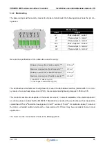
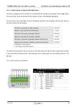
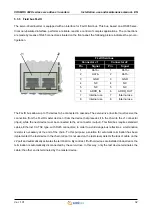
The connector pinout is shown below:

Minimum cross-section of solid conductor

0.20 mm

2

Maximum cross-section of solid conductor

1.5 mm

2

Minimum cross-section of flexible conductor

0.20 mm

2

Maximum cross-section of flexible conductor

1.5 mm

2

Minimum cross-section of flexible conductor with terminal

0.25 mm

2

Maximum cross-section of flexible conductor with terminal

0.75 mm

2

*= Use 60/75 °C wires only (UL)
**= Use Copper Conductors only (UL)

Auxiliary power supply and 24V digital inputs  

Pin

Marking

Signal

1

24VDC+

24VDC power supply - positive

2

24VDC-

24VDC power supply - negative

3

Vs

24VDC sensor power supply

4

In1

Digital input 1

5

In2

Digital input 2

6

In3

Digital input 3

7

In4

Digital input 4

8

GND

Ground

1 2 3 4 5 6 7 8

Содержание COSMOS 302 Series

Страница 1: ...t Installation use and maintenance manual SERVO DRIVES COSMOS 302X SERIES BEFORE STARTING UP THE SERVO DRIVES COSMOS 302X SERIES CAREFULLY READ THIS MANUAL AND FOLLOW ALL INSTRUCTIONS IN ORDER TO ENSU...

Страница 2: ...4 4 6 Accessories 15 4 7 Electromagnetic compatibility EMC 15 4 8 Mechanical specifications 16 4 8 1 Weight 16 4 8 2 Model size 16 5 Installation and start up 17 5 1 Preliminary operations 17 5 2 Posi...

Страница 3: ...essed to the following professionals The present instructions must be made available to all the above individuals User User is a person a company or an institution that buys the equipment and uses it...

Страница 4: ...AKE ANY INTERVENTION BEFORE INTE GRALLY READING AND UNDERSTANDING THIS MANUAL IN PARTICULAR ADOPT ALL SAFETY PRECAUTIONS AND PRESCRIPTIONS INDICATED IN THIS MANUAL THE EQUIPMENT MUST BE USED FOR PURPO...

Страница 5: ...ming the activities described later on in this manual These prescriptions constitute the prescribed method of operating the device in a way that is safe for person nel equipments and environment The s...

Страница 6: ...drawings in this manual might have been modified later always refer to the latest version All upgrades can be requested to SMITEC S p A directly Make sure that the personnel is qualified and adequate...

Страница 7: ...least 6 minutes earlier and that the motor is still Avoid any metal components screws electrical cables fall into the driver during the in stallation because they might cause short circuits The driver...

Страница 8: ...rticular care not to touch the parts of the equipment in these cases or use special protections and precautions during handling HOT SURFACE RISK OF BURN Les pi ces de l appareil peuvent atteindre une...

Страница 9: ...rent delivered and on the input power input The power section is made with the latest generation of intelligent IGBT modules efficient and reliable Various diagnostic features are available to protect...

Страница 10: ...erating temperature 0 40 C with full load operation 0 55 C with derating of the supplied torque Pollution degree UL Use in Pollution degree 2 Environment Maximum surrounding air temperature UL 0 40 C...

Страница 11: ...allowed TT TN Maximum short circuit current 5 kA at the point of installation Current max main power supply 10 A RMS 24VDC auxiliary power supply voltage 24 VDC 15 20 ripple max 5 of the nominal valu...

Страница 12: ...ual EN Ver 1 01 12 4 3 4 Digital inputs Peak output current 12 A Protections Phase to phase short circuit overload servo drive overtemperature Number of inputs 4 Type 24V digital inputs compatible wit...

Страница 13: ...current and the release These data are indicated on the driver label Order code Model Description KZ010525 COSMOS 3020 FA 2X12Apk FLxIO ASYNC TYPE Series 3 3000 Peak current 01 14Apk 0 75kW 02 2 x 12...

Страница 14: ...m 0 Absent 1 Present Dynamic brake 0 Absent 1 Present Brake resistor 0 Absent 1 2 5kJ 2 5 0kJ 3 4 0kJ 4 0 8kJ Encoder 0 Absent 1 Incremental 5V diff phases and HALL T T L Hiperface 2 Hiperface 3 Incre...

Страница 15: ...made by means of an adequately sized shielded cable The shielded cable must be connected to earth on both sides with low RF impedance connection The motor type and size are suitable for the servo driv...

Страница 16: ...series servo drives inverters Installation use and maintenance manual EN Ver 1 01 16 4 8 Mechanical specifications 4 8 1 Weight The following table shows the weight 4 8 2 Model size Type Weight kg KZ0...

Страница 17: ...must be duly tightened to the metal wall of the electrical panel by means of two screws M5 x 0 8 mm if the operation generates vibrations use retention washers Grover or Belleville or a thread lock co...

Страница 18: ...itioner In order to avoid dust ingress which might degrade the dissipater performance it is recommended to use filters The conditioning system must be adequately sized by taking into consideration the...

Страница 19: ...c tions mains power supply motor outputs PE Ground protective conductor while the extra low voltage con nections 24V power supply 24V digital inputs are made via detachable connectors 5 3 1 Connection...

Страница 20: ...h TT or TN distribution systems the picture shows the recom mended wiring diagram WARNING Risk of Electric Shock wait at least No 360 seconds 6 minutes after disconnecting power Risque de choc lectriq...

Страница 21: ...ovided by the Standards In this case an additional external filter may be necessary Due to the extremely variable operating conditions number of servo drives cable length total current values required...

Страница 22: ...rent therefore it is necessary to carefully choose the protective devices In case of failure the input current might include a significant direct component if no fuse is used for protection install a...

Страница 23: ...ceeded If protection against short circuits is provided by partial range fuses such as aR type the overload protection must be provided in other ways for example with circuit breakers If the servo dri...

Страница 24: ...ed current 16 A Working voltage 700V AC Suitable For Use On A Circuit Capable Of Delivering Not More Than 5000 Arms Symmetri cal Amperes 230 Vac Maximum when protected by semiconductor fuses model FR1...

Страница 25: ...consider that the EN 60204 1 Standard does not allow the use of cables with a cross section smaller than 0 75 mm2 inside the housings and 1 0 mm2 outside 0 75 mm2 for multicore cables To connect the...

Страница 26: ...s on the order in which the phases U V and W are connected To re verse the rotation of an asynchronous motor simply invert two phases in case of a brushless motor an incor rect connection of the phase...

Страница 27: ...ntact At the same time insert the cable It is recommended to use a screwdriver with a 2 5 mm flat head The connector pinout is shown below Minimum cross section of solid conductor 0 20 mm2 Maximum cro...

Страница 28: ...the limits of the servo drive see specific paragraph If this volt age is outside the prescribed limits the servo drive may be damaged For safety reasons the auxiliary power must be supplied by a PELV...

Страница 29: ...made by means of an ordinary unshielded cable However if the operating environment is affected by significant electrical noise or the distances to be crossed are significant the use of a shielded cab...

Страница 30: ...DC and have differential output signals Differential outputs offer grater noise rejection than common single ended outputs When brushless motors are used it is necessary to know also the rotor initial...

Страница 31: ...red directly to the connector shell Connect the other end of the shield to the encoder housing when possi ble Since differential signals are involved each pair of signals such as U and U must be carri...

Страница 32: ...evice must be connected to the J2 connector output This field bus requires standard cables Ethernet CAT 5E type with RJ45 connectors in order to avoid dangerous reflections a termination resistor is n...

Страница 33: ...0 and F can not be used on the same bus each device must have a different address The Cosmos 302X being a double inverter uses two addresses simultaneously the one set via the rotary switch and the n...

Страница 34: ...r details about FLxIO bus operation and types of connection please refer to the specific documenta tion 5 3 5 2 Automatic addressing Currently automatic addressing is not active Make sure the address...

Страница 35: ...on This operation can be implemented directly via the FLxIO fieldbus teleprogramming if the master device de tects that the servo drive is programmed with a FW version different from the one loaded in...

Страница 36: ...d in its original package for the necessary period it must be kept in a covered area even if it is packed Protect the equipment from dust and weather Do not stack more than 10 servo drives in order to...

Страница 37: ...enance SMITEC S p A does not require any ordinary maintenance to be performed on servo drives inverters of the COSMOS 302X series remember that no component may be removed from the device since such r...

Страница 38: ...of in compliance with the legislation in force in the country where it is in stalled In case of partial disposal of the equipment frame dissipater electronic boards the different materials must be se...

Страница 39: ...Fanless 9 Field bus FLxIO 32 Firmware 35 I Incremental encoder 30 M Main power supply 11 20 Manual addressing 33 Marking 10 Max frequency 12 Maximum altitude 11 Model size 16 Motor outputs 11 Motor w...

Отзывы: