No.
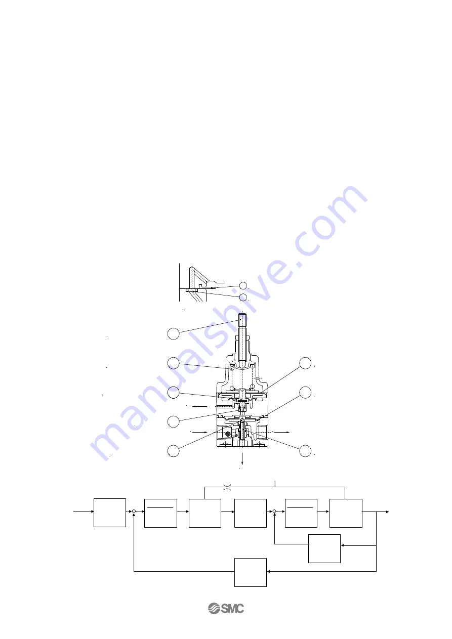
2. Structure and operating principles
When the Adjusting screw
①
is turned, the nozzle
③
is closed by the diaphragm disk
②
, allowing the
supply air that flows in from the upstream side to pass through the fixed orifice
④
and to acts on
diaphragm C
⑥
as nozzle back pressure, the main valve
⑦
is pushed down by the generated force and
the supply pressure flows out to the downstream side. The air pressure that flows in acts on bottom side
of diaphragm C
⑥
and while opposing the force generated by nozzle back pressure, it also acts on
diaphragm A
⑤
opposing the compression force of the setting spring
⑧
and balance with set pressure.
When the output pressure raises above the setting pressure, diaphragm A
⑤
is pushed up which makes
the interval between the diaphragm disk
②
and the nozzle
③
widens, the nozzle back pressure drops,
the pressure balance of upper/bottom part of diaphragms C
⑥
collapses. Then as the main valve
⑦
closes, the exhaust valve
⑨
opens at the same time and the excess pressure from the downstream side
is discharged to the atmosphere. In this way fine pressure variations are detected by the nozzle/flapper
type pilot mechanism, and precise pressure adjustment is performed. Deviation due to pressure
difference between in/outside of bourdon tube is transmitted to the sector through the rod to rotate the
pinion engaging the sector. The indicting needle and scale display the pressure value.
-5-
SUP
OUT
BLEED
E
X
H
5
6
7
9
3
2
8
1
Diaphragm A
Diaphragm C
Main valve
Exhaust valve
Nozzle
Diaphragm disk
Adjusting spring
Adjusting screw
4
Fixed orifice
6
Diaphragm C
SUP.side passage
Setting
spring
N/m
Diaph.C
m
2
Daiph.A
m
2
Nozzle
flapper
MPa/ m
Diaph.B
m
2
spring
Compd
.
1
(B)
m/N
Main valve
MPa/ m
(S)
Displ
m
+
Force
―
N
Displ
m
Press
MPa
+
Force
―
N
Displ
m
Press.
MPa
Force
N
Force
N
SUP
Fixed
orifice
spring
Compd
.
1
(A)
m/N


