background image


-6- 


No.EX##-OMK0004-A 


•Do not use the product in an environment where corrosive gases or fluids could be splashed. 

Otherwise damage to the product and malfunction can result. 

•Do not use in an area where surges are generated. 

If there is equipment which generates a large amount of surge (solenoid type lifter, high frequency induction 
furnace, motor, etc.) close to the SI unit, this may cause deterioration or breakage of the internal circuit of the SI 
unit. Avoid sources of surge generation and crossed lines. 

•When a surge-generating load such as a relay or solenoid is driven directly, use an SI unit with a built-in 

surge absorbing element. 

Direct drive of a load generating surge voltage can damage the SI unit. 

•The product is CE marked, but not immune to lightning strikes. Take measures against lightning strikes 

in the system. 

•Prevent foreign matter such as remnant of wires from entering the SI unit to avoid failure and 
malfunction. 

Otherwise failure or malfunction can result. 

•Mount the product in a place that is not exposed to vibration or impact. 

Otherwise failure or malfunction can result. 

•Do not use the product in an environment that is exposed to temperature cycle. 

Heat cycles other than ordinary changes in temperature can adversely affect the inside of the product. 

•Do not expose the product to direct sunlight. 

If using in a location directly exposed to sunlight, shade the product from the sunlight. 
Otherwise failure or malfunction can result. 

•Keep within the specified ambient temperature range. 

Otherwise malfunction can result. 

•Do not operate close to a heat source, or in a location exposed to radiant heat. 

Otherwise malfunction can result. 


Adjustment and Operation 

•Set the switches by using a sharp-pointed screwdriver etc. 

It may damage set switches. 

•Perform settings suitable for the operating conditions. 

Incorrect setting can cause operation failure. 
For details of each setting, refer to page 16 to 17 of this manual. 

•Please refer to the PLC manufacturer's manual etc. for details of programming and addresses. 

For the PLC protocol and programming refer to the relevant manufacturer's documentation. 


Maintenance 

•Turn off the power supply, stop the supplied air, exhaust the residual pressure and verify the release of 

air before performing maintenance. 

There is a risk of unexpected malfunction. 

•Perform regular maintenance and inspections. 

There is a risk of unexpected malfunction. 

•After maintenance is complete, perform appropriate functional inspections. 

Stop operation if the equipment does not function properly. 
Otherwise safety is not assured due to an unexpected malfunction or incorrect operation. 

•Do not use solvents such as benzene, thinner etc. to clean the SI unit. 

They could damage the surface of the body and erase the markings on the body. 
Use a soft cloth to remove stains. 
For heavy stains, use a cloth soaked with diluted neutral detergent and fully squeezed, then wipe up the stains 
again with a dry cloth. 


Содержание EX250-SEN1

Страница 1: ...No EX OMK0004 A PRODUCT NAME SI unit for EtherNet IPTM MODEL Series Product Number EX250 SEN1 ...

Страница 2: ... 10 Installation 10 Position of end plate 11 Wiring 12 LED Indication and Settings 15 EtherNet IPTM CONFIGURATION WITH RSLogix5000TM 18 Maintenance 19 Troubleshooting 20 Specifications 26 Specifications 26 Dimensions 29 Option 30 Refer to the operation manual EX250 IE1 IE2 IE3 for the input block specifications and EX9 OET1 OET2 OEP1 OEP2 PE1 for the output block and power block specifications ...

Страница 3: ... of equipment failure when configuring the equipment 2 Only personnel with appropriate training should operate machinery and equipment The product specified here may become unsafe if handled incorrectly The assembly operation and maintenance of machines or equipment including our products must be performed by an operator who is appropriately trained and experienced 3 Do not service or attempt to r...

Страница 4: ...placement product or necessary parts will be provided This limited warranty applies only to our product independently and not to any other damage incurred due to the failure of the product 3 Prior to using SMC products please read and understand the warranty terms and disclaimers noted in the specified catalog for the particular products 2 Vacuum pads are excluded from this 1 year warranty A vacuu...

Страница 5: ...atmosphere containing flammable or explosive gases Fire or an explosion can result This product is not designed to be explosion proof If using the product in an interlocking circuit Provide a double interlocking system for example a mechanical system Check the product regularly for proper operation Otherwise malfunction can result causing an accident The following instructions must be followed dur...

Страница 6: ...m Repetitive bending stress or tensile stress can cause breakage of the cable Wire correctly Incorrect wiring can break the product Do not perform wiring while the power is on Otherwise damage to the SI unit and or I O device can result causing malfunction Do not route wires and cables together with power or high voltage cables Otherwise the SI unit and or I O device can malfunction due to interfe...

Страница 7: ...unlight shade the product from the sunlight Otherwise failure or malfunction can result Keep within the specified ambient temperature range Otherwise malfunction can result Do not operate close to a heat source or in a location exposed to radiant heat Otherwise malfunction can result Adjustment and Operation Set the switches by using a sharp pointed screwdriver etc It may damage set switches Perfo...

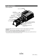
Страница 8: ...onnecting to EtherNet IPTM EtherNet IPTM and the input and output equipment communicate through the SI unit Up to 32 inputs can be connected to the SI unit using Input blocks Up to 32 outputs from combined EX9 Output blocks and valve manifolds can be connected to the SI unit The maximum output point is 24 when the Power block is connected ...

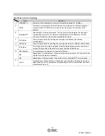
Страница 9: ... and receiving simultaneously for bilateral communication H Half duplex Communication method by sending and receiving alternately for bilateral communication I IP address A 32 bit sequence of numbers assigned to identify individual equipment connected to a network All connected to the network are given individual IP addresses MAC address A number unique to equipment connected to Ethernet MS Abbrev...

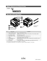
Страница 10: ...Output block connector Connects the solenoid valve Output block etc 5 Display LED display showing the SI unit status 2 6 Switch protective cover Incorporates the internal switch setting IP address and communication method 2 7 Ground terminal Used for grounding 8 MAC address A unique MAC address of 12 hexadecimal number digits to each SI unit 1 For wiring method refer to subsection Wiring page 12 i...

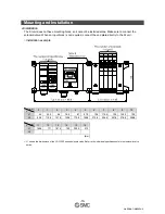
Страница 11: ...connect the end plate directly to the SI unit Installation example L 0 1 2 3 4 5 6 7 8 9 10 L1 45 55 5 66 76 5 87 97 5 108 118 5 129 139 5 150 L2 89 8 110 8 131 8 152 8 173 8 194 8 215 8 236 8 257 8 278 8 299 8 L 11 12 13 14 15 16 L1 160 5 171 181 5 192 202 5 213 L2 mm L1 shows the dimensions of the VQC1000 series solenoid valve Refer to the individual specifications for other solenoid valve serie...

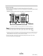
Страница 12: ...locks The number of Power Blocks m L 1 2 3 4 5 6 7 8 9 10 L 114 135 156 177 198 219 240 261 282 303 mm Each dimension shows the SI unit without solenoid valves connected and with the end plate R on the Output block side connected Standard settings of L dimensions are with 10 or less m blocks Contact SMC sales for the setting with over 10 blocks mounted Refer to the specification for each dimension...

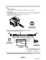
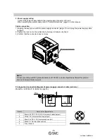
Страница 13: ...ket of SI unit plug the Ethernet communication cable plug 2 Tighten the lock nut on the cable side by turning it clockwise by hand 3 Confirm that the connector does not move Pin layout and connection diagram of Ethernet communication cable Model No EX9 AC EN PSRJ Refer to page 30 Cable specifications Core wire AWG 26 Sheath color Blue green Refer to Media Planning and Installation Manual of ODVA f...

Страница 14: ...nut on the cable side by turning it clockwise by hand 3 Confirm that the connector does not move NOTE D class grounding with the ground resistance of 100 ohm or less should be performed for ground terminal and ground at one point Pin layout and connection diagram of power supply connector cable unit mm Model No EX500 AP S Refer to page 30 Pin No Cable color Signal name 1 Brown 24 VDC 10 5 for sole...

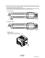
Страница 15: ...two power supply systems can be adopted however the wiring should be made separately for solenoid valves output and for input and control for both systems A Two power supplies B Single power supply 3 Ground terminal Connect the ground terminal to ground Resistance to ground should be 100 ohms or less ...

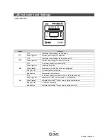
Страница 16: ... supply for control is OFF Green light ON Operating normally Green flashes Setting error Device has not been configured Red light ON Unrecoverable internal error MS Red flashes Recoverable internal error OFF The power supply for control is OFF or IP address not set Green light ON EtherNet IP TM level communication not established Green flashes Multiple EtherNet IP TM level communications establish...

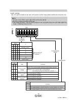
Страница 17: ...a sharp pointed watchmakers screwdriver etc NOTE 1 Be sure to turn off the power supply before setting the switches 2 Be sure to set these switches before use 3 After setting the switch close the switch protective cover and tighten the screws with proper tightening torque Tightening torque 0 6 Nm ...

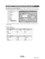
Страница 18: ...ng this function will disable the EX250 to retrieve its boot information from the BOOTP DHCP Server and causes the EX250 to retain its current configuration during the next power up 2 DHCP Mode SW1 Dip switches 1 4 on The IP address is acquired via DHCP Server The IP address is not saved and lost if the power to the EX250 unit is cycled 3 Hardware Addressing The IP address range is 192 168 0 1 192...

Страница 19: ...omation s RSLogix5000TM programming software example PLC software RSLogix5000 TM manufactured by Rockwell Automation is shown above RSLogix5000 TM is a registered trademark of Rockwell Automation Connection Parameter Assembly Instance values Description Decimal Comm Format Data INT Data SINT Input 100 100 Output 150 150 Configuration 1 1 Size Description Size Comm Format Data INT Data SINT Input 3...

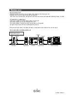
Страница 20: ...ws with specified tightening torque 0 6 Nm Precautions on maintenance 1 Be sure to check that all the power supply is turned off 2 Foreign matters must not be intruded in the unit 3 Foreign matters or scratches must not be present on the gasket 4 Tighten the screws with the specified tightening torque If they are not set properly the failure of board or liquid and or dust intrusion the unit can re...

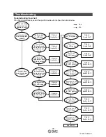
Страница 21: ...ot operate The Input block PWR_LED goes off Only the input signal LED of the Input block do not lights up Refer to trouble No 2 Refer to trouble No 3 Refer to trouble No 4 Refer to trouble No 5 Refer to trouble No 6 The SI unit PWR_LED goes off Refer to trouble No 7 The SI unit SOL_LED goes off Refer to trouble No 8 The SI unit MS_LED goes off Refer to trouble No 9 The red SI unit MS_LED flashes R...

Страница 22: ...e power supply for solenoid valve and the power supply for output Check that there is no incorrect wiring of the power supply cable Review the wiring condition of the power supply cable Failure of the power supply for the solenoid valve and output Check the supply voltage to the power supply for the solenoid valve and output Supply 24 VDC 10 5 to the power supply for the solenoid valve and output ...

Страница 23: ...tch those of the solenoid valve and output block common common Use common with the solenoid valve and Output block suitable for the PNP output of the SI unit Check the troubleshooting for the solenoid valve Correct the trouble of the solenoid valve Only the solenoid valve Output block LEDs do not light up Failure of the solenoid valve and or Output block Replace the SI unit with new one and operat...

Страница 24: ...se Investigation method of cause Remedy Inconsistent polarity in sensors Check the specifications of the Input block NPN PNP match those of the sensor Make a suitable combination of Input block and sensor Incorrect connection of the sensor Check that the sensor cable is not broken and that the connection between the sensor cable and connector has not loosened Review the connection condition of the...

Страница 25: ...Abnormal status of the SI unit Check if the power supply line is in the same route as the power line and or high voltage line Separate the power supply cable from the power line and or high voltage line and restart the power supply of the SI unit Trouble No 10 Trouble Possible cause Investigation method of cause Remedy Check if the Earth terminal is grounded Provide grounding to improve the noise ...

Страница 26: ...Possible cause Investigation method of cause Remedy Check that there is no broken communication line or loosened connector Review the connection condition of the communication line If the cable is broken replace it with a new one The red SI unit NS_LED flashes Broken communication line Check if the PLC is operating normally Review the setting of PLC Trouble No 16 Trouble Possible cause Investigati...

Страница 27: ...Unit 0 1 A Input device 1 A Power supply for output Max 2 A Number of input output points Input point Max 32 Output point Max 32 Output type PNP negative common source The maximum output point is 24 when the Power block is connected Communication specification Item Specification Protocol Ethernet IEEE802 3 Media 100BASE TX Communication speed 10 M 100 Mbps Automatic selection or manual setting Max...

Страница 28: ... L L L L L L L L L Fixed to Low Status input area Diagnostic Status input area Item Status Condition 0 No supply voltage SP Status of solenoid power supply 1 Supply voltage OK 0 Short circuit DI Status of sensor power supply 1 Normal Output area mapping Output data MSB LSB MSB LSB Offset word 15 8 7 0 0 15 14 13 12 11 10 9 8 7 6 5 4 3 2 1 0 1 31 30 29 28 27 26 25 24 23 22 21 20 19 18 17 16 Sensor ...

Страница 29: ...e output on B side will be empty See Fig a Special wiring specification with a mixed wiring of single solenoid and double solenoid can be specified with a wiring specification sheet This makes it possible to specify the output numbers without empty outputs See Fig b Each bit status 0 or 1 of the data shows the ON or OFF solenoid valve status 0 OFF 1 ON and the output number starting from 0 will be...

Страница 30: ... 29 No EX OMK0004 A Dimensions ...

Страница 31: ...ion cable For details refer to subsection Wiring page 12 in this manual Hot to order 2 Power supply cable For details refer to subsection Wiring page 13 in this manual Hot to order 3 Spare fuse for Input block Hot to order 4 Output cable Hot to order ...

Страница 32: ... cable for power input connector of Power block Hot to order 6 Power supply cable for power supply connector of Power block Hot to order 7 Input block relay connector cable Hot to order 8 Input block assembly type connector Hot to order ...

Страница 33: ...rder 11 Waterproof cap Mounted on the unused ports of the Input block Output block and Power block Proper use of this waterproof cap can achieve IP67 enclosure The waterproof caps are delivered together with the Power block as accessories Hot to order NOTE Tighten the waterproof cap with the specified tightening torque 0 05 Nm for M8 0 1 Nm for M12 ...

Страница 34: ... history A Add some contents Note Specifications are subject to change without prior notice and any obligation on the part of the manufacturer EtherNet IP TM is a trademark of ODVA 2007 2012 SMC Corporation All Rights Reserved ...

Отзывы: