background image

12

 / 

49


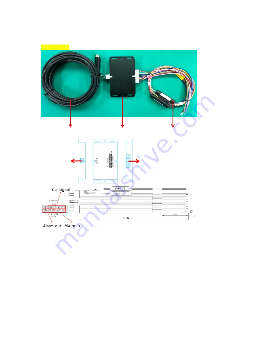
Junction


box


1.


ACC IN (White)   

2.


Alarm IN 1 (Sky Blue): Voltage ON / OFF   

3.


Alarm IN 2 (Sky Blue): Voltage ON / OFF   

4.


Alarm IN 3 (Sky Blue): Normal OPEN / CLOSE 

5.


Alarm IN 4 (Sky Blue): Normal OPEN / CLOSE 

6.


Alarm OUT1B (Pink) 

7.


Alarm OUT1A (Pink) 

8.


Alarm OUT2B (Pink) 

9.


Alarm OUT2A (Pink)   

10.


B (Red)   

11.


Left signal (Green) 

12.


Right signal (Yellow)   

13.


Brake signal (Blue) 

14.


Reverse signal (Brown) 

15.


Speed Pulse (Violet) 

16.


RPM (Orange) 

17.


Battery – (Black)   

18.


Battery _ (Black) 

Extension cable from 

BX2000

Junction box 

Signal and Power cable 

Signal and Power cable 

from vehicle. 

Extension 

cable 

From 

BX2000

Содержание BX2000

Страница 1: ...1 49 BX2000 USER GUIDE Ver 2 1 0 Thank you for purchasing SmartyHD Please read this USER GUIDE carefully before using this Drive Recorder Please keep this USER GUIDE in an easily accessible location ...

Страница 2: ...2 49 Rear Side G Sensor Calibration button Panic button SD Slot 2 Slave SD SD Slot 1 Master SD Red LED Over speed 2 Orange LED Over speed 1 Blue LED Record Green LED Communication GPS ...

Страница 3: ...ill be automatically started after power on The normal record files will be made every 10 minutes LED operation of the Continuous record The blue LED is blinking slowly Event record The event recording will be automatically started by G sensor or Panic button or Alarm G sensor sensitivity can be set with your PC Each event file contains up to 20 seconds prior up to 20 seconds post event And the ev...

Страница 4: ...record file will be stored on the SD slot No 2 Picture 2 fps setting 30fps Pre Post time 15 sec LED operation of the Dual The Blue LED is blinking slowly during normal recording and the blue LED is blinking fast during event recording Buzzer sound operation of the Dual record Ping pong Ping pong when an event triggered Remark Beep Beep Beep Beep Beep Beep sound will occur when SD error or SD full ...

Страница 5: ...eeding 2 80 Km LED operation of the over speeding Over Speeding1 The orange LED lights up for 5 seconds Over Speeding2 The Red LED lights up for 5 seconds Buzzer sound operation of the over speeding Trigger sound will be Ping pong Ping pong said when the over speeding occurs both excessive speed 1 and 2 SD card initialization Insert the SD card you want to initialize then connect the power Press a...

Страница 6: ... Once the BLUE LED light is off insert the SD memory card This product can be used up to two SD card Please insert the master SD which has the Setting ini file at SD slot No 1 Inserting the 3G 4G USB modem Turn off the power and then check the BLUE LED light Once the BLUE LED light is off insert the 3G 4G USB modem LED Buzzer Specification Red LED Over speed 2 Orange LED Over speed 1 Blue LED Reco...

Страница 7: ... Over Speed 1 On Pirippiri tsu 1 times Over Speed 2 On Pirippiri tsu 1 times G sensor calibration Beep about 3 s econds Pong SD card initialization Simultaneous flashing Beep 2 seconds Firmware Upgrade Flashing sequentially SD card full Flashing 3 times blink Long Extinction About 3 se conds beep 3 times Error Record error Simultaneous flashing beep 3 times Camera 2 video loss Simultaneous flashin...

Страница 8: ...ile There is a possibility of lost the last event file During dual recording The continuous video recording will be recorded up to just before the end of the power When the power ACC off is off and simultaneously an event is triggered there is no time to record the event file There is a possibility of lost the last event file Continuous record Power OFF Record OFF Flash memory SD Card Event Post P...

Страница 9: ...S G Sensor Internal 3 axis G sensor Memory 2 x SDHC flash memory card support 4GB 8GB 16GB 32GB Max 32GB 32GB RTC Internal battery Buzzer Recording start error LED 4 LED Red Orange Blue Green Super Capacitor Enable recording last file and shut down PC software PC Viewer Alarm In Cigar Jack N A Power Adapter 1 EA Junction Box 4 EA Alarm Out Cigar Jack N A Power Adapter 1 EA Junction Box 4 EA Signal...

Страница 10: ...R 15 2 1 4 3 8 6 17 2 1 1 6 1 12 2 24 4 48 8 HIGH 15 HIGH 15 2 7 5 4 10 8 21 6 1 1 7 6 15 3 30 6 61 1 Normal 15 Normal 15 3 7 7 3 14 6 29 3 1 1 10 2 20 4 40 9 81 7 VGA 640x480 SUPER 30 HD1 720x240 SUPER 30 2 8 5 7 11 4 22 8 1 1 13 2 26 3 52 7 105 4 HIGH 30 HIGH 30 3 6 7 3 14 6 29 2 1 1 16 5 33 0 66 1 132 2 Normal 30 Normal 30 5 1 10 1 20 3 40 6 1 1 22 1 44 3 88 6 166 7 QVGA 320x240 SUPER 30 CIF 35...

Страница 11: ... 450 Events 900 Events 1800 Events 2000 Events NORMAL 30 NORMAL 30 700 Events 1400 Events 2000 Events 2000 Events BX2000 Recording Time Table Dual Recording Camera1 Camera2 Record Folder 4GB 8GB 16GB 32GB Resolution Quality FPS Resolution Quality FPS VGA 640x480 SUPER 1 D1 720x480 SUPER 1 Norma l folder 5 hours 10 hours 20 hours 40 hours 30 30 Event folder 185 Events 370 Events 740 Events 1480 Eve...

Страница 12: ...LOSE 6 Alarm OUT1B Pink 7 Alarm OUT1A Pink 8 Alarm OUT2B Pink 9 Alarm OUT2A Pink 10 Battery Red 11 Left signal Green 12 Right signal Yellow 13 Brake signal Blue 14 Reverse signal Brown 15 Speed Pulse Violet 16 RPM Orange 17 Battery Black 18 Battery _ Black Extension cable from BX2000 Junction box Signal and Power cable Signal and Power cable from vehicle Extension cable From BX2000 ...

Страница 13: ...ch No Time 4 5 OFF OFF 0 Sec ON OFF 5 Sec OFF ON 10 Sec ON ON 30 Sec 5 Not Used DIP Switch No Description 6 7 Not used Not used Not used 4 12V 24V Select Setting DIP Switch No Voltage 8 OFF 12 V ON 24 V Input Voltage DC 12V 24V 2A Output Voltage DC 5V 3A Operation Temp 20 60 When it use at 12V car When it use at 24V car Initial Voltage To turn on the unit 12 39V Initial Voltage To turn on the unit...

Страница 14: ...ery voltage dropped below 12V or 24V Input Voltage DC 12V 24V 2A Output Voltage DC 5V 3A Operation Temp 20 60 When it use at 12V car When it use at 24V car Initial Voltage To turn on the unit 12 5V Initial Voltage To turn on the unit 23 2V Power Cut Voltage 12V 0 2V Power Cut voltage 22V 0 4V Extension cable from BX2000 Power Adaptor Power cable Power cable From Vehicle Extension cable from BX2000...

Страница 15: ...15 49 Cigar Power DC 12V only 12V to 5V Converter Inside 5m cable ...

Страница 16: ...e on screen instructions to install the software The following icon appears on your PC if you check create a desktop icon during installation BX2000 Analysis Software Icon Description and execution of BX2000 Analysis Software Insert the SD Card of BX2000 and double click the icon of BX2000 Analysis Software then the main screen will be displayed as follows Description of BX2000 Analysis Software s...

Страница 17: ...Privacy settings File list Tracking map Drive data Event Search Previous Frame Reverse Play Pause Play Next Frame Volume Play back Speed Capture Screen Record Video Vehicle ID Driver ID Right Brake Reverse Left Panic event recordi ng file G Sensor event recordin g file Alarm event record ing file Car Signal event recording file Speed event recordin g file Video Loss Speed RPM Analyze Driving Info ...

Страница 18: ...rd Reader After confirming that SD card is recognized correctly in the PC click the Select SD Card button and the window for Select SD card shows up Select SD card drive and Click Open SD Card button The list of data tab continuous and event is displayed on the right side of the screen The recorded data is displayed under each tab as shown below To play video click the file you want to play from t...

Страница 19: ...ata BX2000 can record not only video and audio GPS information speed but also vehicle information like the alarm G Sensor and left right blinker brake back speed Pulse RPM together The recorded information can be analyzed and played through PC Viewer software The default setting only displays the G sensor graphs but other information may be added by checking the boxes in the upper part of the scre...

Страница 20: ...m right corner choose the date you wish to inspect among the dates highlighted in blue Dates that are not highlighted in blue do not have the relevant data All data from the selected date will be automatically chosen from the selection on the right You can unselect data that you do not need Click load for access The time span for the data selected cannot exceed 24 hours ...

Страница 21: ...ws the state of the engine where white means the engine is off blue means it is running properly within the pre set RPM limit and red means over acceleration i e exceeding the pre set RPM limit The lower graph shows the G sensors where the x axis is in red y axis in blue and z axis is green The indicator bar right below shows jolts in the G sensor values i e G sensor values that exceed the pre set...

Страница 22: ...than the set amount of time will be regareded as excessive The RPM value can be set from 0 999 RPM and the time can be set by scrolling down and selecting the appropriate value RPM that exceed the RPM limit but for less than the set amount of time will not be counted as excessive speed Eco speed Limit This sets the criteria for excessive eco speed i e speeds that exceed this value for more than th...

Страница 23: ...ey would be graded as B This criterion is used in both safety and eco grading but the weights can be set separately The assessment of this criterion is based on the Acceleration Brake component in the analysis criteria settings Sudden Acceleration Count per hour This sets the grading criterion for sudden acceleration per hour Since it is an average for the whole duration of the drive it can be set...

Страница 24: ...verage speed in relation to the speed limit The value is set in km h and can be set from 999 to 0 km h This criterion is used only for safety grading The assessment of this criterion is based on the Speed Limit in the analysis criteria settings Excess Eco speed Count per hour This sets the grading criteria for eco speeding and is calculated per hour Since it is an average for the whole duration of...

Страница 25: ...er Analysis software to ease in setting multiple Analysis software Grading Method Grades Each criterion is given a grade of A B C D and anything lower is given a grade of F for fail The set value for each grade is the lower limit and all scores that are lower in value including the set limit will be given that particular grade Any score exceeding this value will be given a lower grade and all scor...

Страница 26: ...ings menu Click the Graph Display Settings button to launch the below window MaxSpeed The graph s upper speed limit can be set here from 0 to 999 km h MaxGSensor The graph s upper g sensor limit can be set here scrolling down and selecting from 1G 2G 3G MaxRPM The graph s upper RPM limit can be set here from 0 to 9999 Zoom Window Display Time The time scale for the zoom graph can be set here scrol...

Страница 27: ...is connected to the internet correctly The BX2000 Analysis Software is composed of a main screen drive data screen drive data analysis screen and the tracking screen These screens can be displayed independently and their location and size changed to improve use and management of data In addition it is also possible to display in the multiple monitors By using different screen modes of Viewer softw...

Страница 28: ...he vast amounts of video and audio recordings Click the Event Search button to access the event search screen Firstly set the search range Date and Time If you select the type of events you want to search for like G sensor signal alarm speed etc and then click the Search button Select the data you want to play from the list and click the Go to Video button and the video that you selected is displa...

Страница 29: ...n pause and click the Privacy settings button Privacy setting screen will pop up Using the scroll down select the camera you wish to set up On the selected camera view blur out the area you wish to protect by left clicking on the sections You can select multiple areas You can also unselect selected areas by right clicking the blurred areas To select all or clear all click on the Select all or UnSe...

Страница 30: ...ave Check all the information you want to include from the options shown The selected information will be imprinted on the image itself Choose the folder you want to save the image to and click start Still frame from the all selected cameras at the paused instance will be saved as jpg files in the folder It will be saved in the default folder of My Documents SmartWitness BX2000 JPG if you do not s...

Страница 31: ...tically set to the time that was paused at the start of this process and cannot be changed Select the frame rate FPS from 1 to 30 you wish to use For the most natural video stream use 30 FPS Check the supplementary information you wish to include in the video The selected the information will show up as text on the video itself Choose the folder you wish to save the AVI file and type a file name T...

Страница 32: ...k all camera images you wish to include in the report Type the title of the report and any comments about the situation or other reminders If the Privacy Masking box is checked the pre set blur effect will be applied When you click OK a preview of the report like the one below will be pop up After checking all the information press Print to print the report ...

Страница 33: ...e start time is when the video was paused and cannot be changed once you start this process Input all the information you wish to include in the back up file including DVR ID User ID title and comments Select the folder where you wish to save the backup file The default folder is My Documents SmartWitness BX2000 BACKUP To ease management of the backup files choose a type in or later select from th...

Страница 34: ...ckup files are at the bottom of the screen It will automatically show the last folder that was accessed Select the report type by scrolling down the options The files are listed showing the Date Time Vehicle ID Driver ID Title Check the box next to the file you wish to play back click OK The below file list will pop up Double click the file and video files will show on the Viewer ...

Страница 35: ...e password that you set once BX2000 Analysis Software Settings Language Selectable from Japanese Korean English Spanish Russian Velocity form Selectable from km h or mile h Speed type Play information bar Selectable from the vehicle speed pulse or GPS Time unit Selectable from 24HR or AM PM Date Format Selectable from YY MM DD MM DD YY or DD MM YY Default Layout The program will launch with the De...

Страница 36: ...36 49 About You can check the version information of the BX2000 Analysis software Click the About button to see the below pop up You can check the Analysis software version and BX2000 firmware version ...

Страница 37: ...y D TEG Make program folder at SD root folder as below Copy BX2000_X X X bin file in to the SD card program folder Insert the prepared SD card to BX2000 SD slot 1 and turn on the power Upgrading the unit usually takes about 1 to 2 minutes Warning Do not turn off the power during upgrading If the upgrade fails the BX1500 Plus unit should be returned to your local distributor Once the upgrading is f...

Страница 38: ...Ds flash all and buzzer beeps repeated three times Check the following items after you turn OFF the power Make sure that SD card is inserted successfully Check whether locking tab on the SD card is not in the locking position Check whether overwrite setting is turned OFF and SD card is full Data transmission is not done Please check the following items after you turn OFF the power Make sure that U...

Страница 39: ...he PC Initialize SD card Click To initialize the SD card quickly click on the above icon and ou will be presented with the following screen to choose the SD card to initialize Click OK when selected On the following screen check the Quick Format button and uncheck the Backup Configuration File and Click Start to begin initialization ...

Страница 40: ...D Slot 1 Master SD card SD Slot 2 Slave SD card Check Master SD card when you make the Master SD card to insert it to SD slot 1 Uncheck Master SD card when you make the Slave SD card to insert it to SD slot 2 ...

Страница 41: ...wer BX2000 INT1 Power adaptor BX2000 INT2 Junction box Smart Sensor Sensitivity Easy Custom Settings Check box allows you to set the sensitivity to 1 High 2 Middle 3 Low Collision Turning Aceel Decel Uncheck box you can set 3 different Smart Sensor values individually Collision shock Sensitivity 1 3 Turning shock Sensitivity 1 3 and Acceleration Deceleration shock sensor 1 3 Alarm Beep Turn the be...

Страница 42: ...amera Resolution 2nd camera Resolution HD 1280x720 D1 720x480 VGA 640 x480 HD1 720 x240 QVGA 320 x240 CIF 352x240 Recording Mode Continuous Event Continuous Event 1fps continuous recording Event recording adjust the FPS from 1fps to 30fps ...

Страница 43: ... 10 15 5 30 4 30 2 30 1 30 HD 720P 1280x720 15 HD1 720x240 15 10 30 5 30 4 30 2 30 1 30 HD 720P 1280x720 15 CIF 352x240 30 10 30 5 30 4 30 2 30 1 30 VGA 640x480 30 D1 720x480 30 QVGA 320x240 30 D1 720x480 30 Pre Event recording time Post Event recording time Adjust the Pre Post time from 5 sec to 20 ssec Telematics Data GPS data G Sensor data will be recorded with videos and at the same time GPS d...

Страница 44: ...44 49 Event Settings When you use Standard power cable When you use BX2000 INT1 cable When you use BX2000 INT2 cable ...

Страница 45: ...45 49 Info Settings ...

Страница 46: ...46 49 Set your Time Zone Set GPS Time Sync Set your Vehicle ID Set Driver ID Auto Format When the SD card doesnot working properly BX2000 will format the SD card automatically ...

Страница 47: ...47 49 3G LTE Settings Set Dial No and APN for the 3G LTE USB modem communication ...

Страница 48: ...48 49 Server communication Settings Set Server URL Allow Images and event to send it to server ...

Страница 49: ...dg 53 Maewha ro Bundang gu Seongnam Gyeonggi do 463 827 Korea Tel 82 31 706 2514 Fax 82 31 8016 0252 Email dteg d teg com Homepage http www d teg com MADE IN KOREA Copyright 2014 D TEG Security Co Ltd All rights reserved ...

Отзывы: