50
51
English
User manual
smartgyro.es
NOTE:
If the key is moved to the “OFF” position while your SmartGyro Avanza is in motion,
the electronic brakes will activate and stop.
HORN
This button activates a warning sound. Your SmartGyro Avanza must be on for the horn to
be operational. Do not hesitate to use the warning horn, as it can prevent injuries.
SPEED ADJUSTMENT
This dial allows you to preset and limit the maximum speed of your SmartGyro Avanza.
— Turning to the left the maximum speed setting will be slower.
— Turning to the right the maximum speed setting will be faster.
REMOVING THE BATTERY
A handle on the top of the battery compartment makes it easier to lift the battery compart-
ment. The compartment contains the battery, the power cord connection of the charger, the
main circuit breaker (reset button) and the battery fuse.
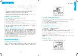
See image 7.
RESET BUTTON
When the battery voltage of your SmartGyro Avanza is exhausted or is very tight due to ex-
cessive loads or steep slopes, the main circuit breaker can be tripped to protect the motor
and electronic components from damage.
7. Battery compartment
Considerations:
— The main reset button of the circuit breaker jumps when the breaker trips.
— When the switch is triggered, the entire electrical system of your SmartGyro Avanza shuts
down.
— Wait a minute or two for the electronic components of your SmartGyro Avanza to “rest”.
— Press the reset button to reset the main switch.
— If the main switch trips frequently, you may have to charge the batteries more frequently.
You may also need your authorized provider to perform a charge test on the batteries of
your SmartGyro Avanza.
— If the main switch trips repeatedly, consult your authorized dealer.
FUSE OF THE CENTRAL CONSOLE
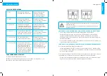
The fuse located under the battery protects the electronic components of the console. See
Image 8.
In the event that any component of the console does not respond, check this fuse, see VIII.
“Basic troubleshooting” and follow the fuse replacement instructions.
8. Fuse compartment.
PROTECTION PANELS
TO REMOVE THE PARTS OF THE PROTECTION PANEL:
1.
Use your finger to locate the push hole behind each protection piece.
2.
Push through the hole to separate the piece.
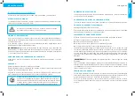
See images 10, 11.
10. Front fender panel
11. Rear fender panel


