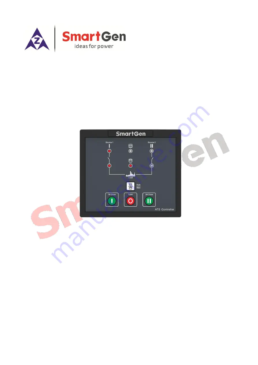
HAT530P/HAT530PC SERIES
ATS CONTROLLER
USER MANUAL
SMARTGEN (ZHENGZHOU) TECHNOLOGY CO., LTD.
Страница 1: ...HAT530P HAT530PC SERIES ATS CONTROLLER USER MANUAL SMARTGEN ZHENGZHOU TECHNOLOGY CO LTD ...
Страница 2: ...including photocopying or storing in any medium by electronic means or other without the written permission of the copyright holder Applications for the copyright holder s written permission to reproduce any part of this publication should be addressed to SmartGen Technology at the address above Any reference to trademarked product names used within this publication is owned by their respective co...
Страница 3: ...TING OF PANEL OPERATION 7 5 1 PANEL OPERATION SETTING 7 5 2 MASTER SETTING 7 5 3 AC SYSTEM SETTING 8 5 4 DELAY ADJUSTMENT 8 5 5 FACTORY RESET DELAY VALUE 9 5 6 AUTO TRANS AUTO RESTORE SETTING 9 6 PARAMETER CONFIGERATION 10 6 1 PARAMETERS TABLE 10 7 OPERATION CONTROL 12 8 WIRING CONNECTION 12 8 1 DESCRIPTION OF CONNECTING TERMINALS 12 8 2 RS485 CONNECTION 14 9 ATS POWER SUPPLY 14 10 TYPICAL WIRING ...
Страница 4: ...n 0 60 seconds and the Genset start delay can be set in 0 3600 seconds The voltage abnormal delay of S1or S2 can be set in 0 60 seconds and the Genset stop delay can be set in 0 3600 seconds S1 Master S2 Master Each Backup and Auto Manual can be set via controller front panel to realize power supply of S1 Master S2 Master or Backup method for each other Closing output signal can be set as pulse or...
Страница 5: ...250V Volts free output Open Relay Output 10A AC250V Volts free output LO Relay Output 16A AC250V Volts free output NO Relay Output 16A AC250V Volts free output Gen Start Relay 7A AC250V Volts free output Communication RS485 interface MODBUS Protocol Case Dimensions 139mmx120mmx50mm Panel Cutout 130mmx111mm Working Conditions Temperature 25 70 C Relative humidity 20 93 RH Storage Condition Temperat...
Страница 6: ...state is abnormal extinguished when there is no S2 power S1 Close Indicator It is illuminated when S1 power auxiliary contactor is active while extinguished when it is deactivated S2 Close Indicator It is illuminated when S2 power auxiliary contact is active while extinguished when it is deactivated Auto Status Indicator It is illuminated when the controller is in auto mode while extinguished the ...
Страница 7: ...nd Auto indicator are illuminated release the three buttons then the auto indicator and S2 power indicators extinguish S1power indicator illuminates which means controller master status can be set b Pressing can circularly set 3 conditions of power supply S1 Master S1 power indicator illuminates and S2 power indicator extinguishes S2 Master S2 power indicator illuminates and S1 power indicator ext...
Страница 8: ...s are flashing 5 times rapidly and controller will work according to the set AC system Once the controller is power on its AC system can be judged by the following four conditions If S1 close indicator illuminates it means Single phase 2 wire system is selected If S1 close indicator manual mode indicator and S2 close indicator illuminate simultaneously it means 3 phase 4 wire system is selected If...
Страница 9: ...ormal delay of 5s and genset shutdown delay of 90s 5 6 AUTO TRANS AUTO RESTORE SETTING Firstly make controller enter parameter setting status and then conduct the setting Set Auto Trans Auto Restore Auto Trans Non Restore Steps a Press and at the same time when S1 S2 power indicator and auto indicator are illuminated simultaneously release the two buttons then the auto indicator and S2 power indic...
Страница 10: ...put pulse 07 Transfer Interval 0 60 s 1 It is the delay from 1 power open to 2 power close or from 2 power open to 1 power close 08 Exceed Transfer 0 20 0 s 0 0 It is the extra output delay of the closing relay after the closing signal has received 09 Start Delay 0 3600 s 1 When voltage is abnormal start delay begins start signal is initiated after the delay has expired 10 Stop Delay 0 3600 s 90 W...
Страница 11: ...ster 1 2 Master 2 Each Backup 28 Auto Trans Auto Restore Set 0 1 1 0 Auto Trans Non Restore 1 Auto Trans Auto Restore 29 Neutral Position 0 1 0 0 With Breaking 1 Without Breaking 30 Module Address 1 254 1 Communication address for module 31 Stop Bit Setting 0 1 0 0 1 stop bit 1 2 stop bits NOTE 1 Parameters above are configured via PC software of SmartGen The PC programming connection is to use RS...
Страница 12: ...ty When it is set to Auto Trans Non Restore controller only transfers to backup power and master power transfer can only be controlled manually Each Backup is for two powers to be backup when S1 power is abnormal S2 is normal then switch will transfer to S2 power supply and vice versa When it is set to Each Backup controller will not detect Auto Trans Auto Restore setting In Manual mode press load...
Страница 13: ...ut Volts free N C output capacity is AC250V16A 18 TD GEN START Genset start output Volts free N C output capacity is AC250V7A 19 20 COM IN Input common port 21 FORCE OPEN Forced open input When it is active set ATS as breaking position and connect with COMM IN 22 COM IN Input common port 23 S1 CLOSE INPUT 1 close input Detect 1 switch close status the auxiliary contact input 24 COM IN Input common...
Страница 14: ...in ATS power supply automatic switching function If the voltage between S1and S2 is normal this can ensure ATS power supply normally by transferring between N O contact output and N C contact output of the intermediate relay 1 2 The output is LO and NO the output value is LN voltage of S1 or LN voltage of S2 The internal wiring connection is shown as below Fig 4 The Internal Wiring Diagram of LO a...
Страница 15: ...HAT530P HAT530PC Series ATS Controller User Manual Page 15 of 18 10 TYPICAL WIRING DIAGRAM Fig 5 SGQ N T Application Diagram Fig 6 FEITENG Application Diagram ...
Страница 16: ... 18 Fig 7 ATyS d Application Diagram Fig 8 Three stage Application Diagram of Motor Type NOTE 1 The diagram is for reference only The actual wiring shall follow the ATS instruction Users should choose proper fuse capacity according to the actual power consumption ...
Страница 17: ...le Phase 2 wire Wiring Diagram NOTE The 2P3W and 1P2W wiring diagrams shown in the pictures above are the AC 220V phase voltage Fig 11 3 phase 3 wire Wiring Diagram NOTE The 3P3W wiring diagram shown in the picture above is the AC 220V line voltage If the actual application is different from it please contact with SmartGen s technical staff to get the specific wiring methods ...
Страница 18: ...HAT530P HAT530PC Series ATS Controller User Manual Page 18 of 18 11 INSTALLATION Unit mm Fig 12 Installation Dimensions _________________________________ ...