Electric charging station WBSH2-7
User Manual and data sheet
13
[A]
Terminal covers
[B]
Cable gland for network cable or ModBus communication cable (RS-485)
[C]
ModBus communication terminals (RS-485) - A + & B +
•
Remove the terminal covers [A] from the rear of the charging station.
•
Loosen the cable gland [B] and insert the cables for ModBus communication.
•
Connect the ModBus communication cables to the respective terminals A + and B +. Finally fix all the cables and
cover the terminal board of the charging station.
Note:
•
If the communication distance is less than 100m, a twisted cable can be used.
•
In caso di rete composta de più stazioni di ricarica, per evitare l’anti-interferenza della rete RS-485 si consiglia di
installare una resistenza da 120Ω in posizione terminale.
Operations
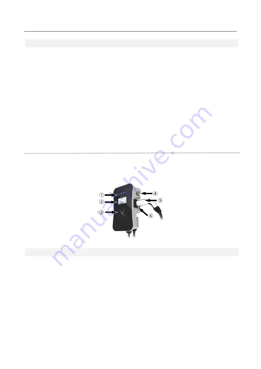
After completing the connection and installation of the WBSH2-7 charging station, it can be started. The “POWER” LED
will turn on and it will mean that the station has gone into Stand-by status. As shown in the figure, the WBSH2-7 charging
station has a panel with which it is possible to interact. The main functions are listed below.
1
LED indicators
4
Emergency button
2
Display LCD
5
Charging socket
3
RFID reader
6
Socket plug


