Functional Description
ATCA-F125 (6873M Artwork) Installation and Use (6806800J94N)
85
4.9
SFP+ Modules
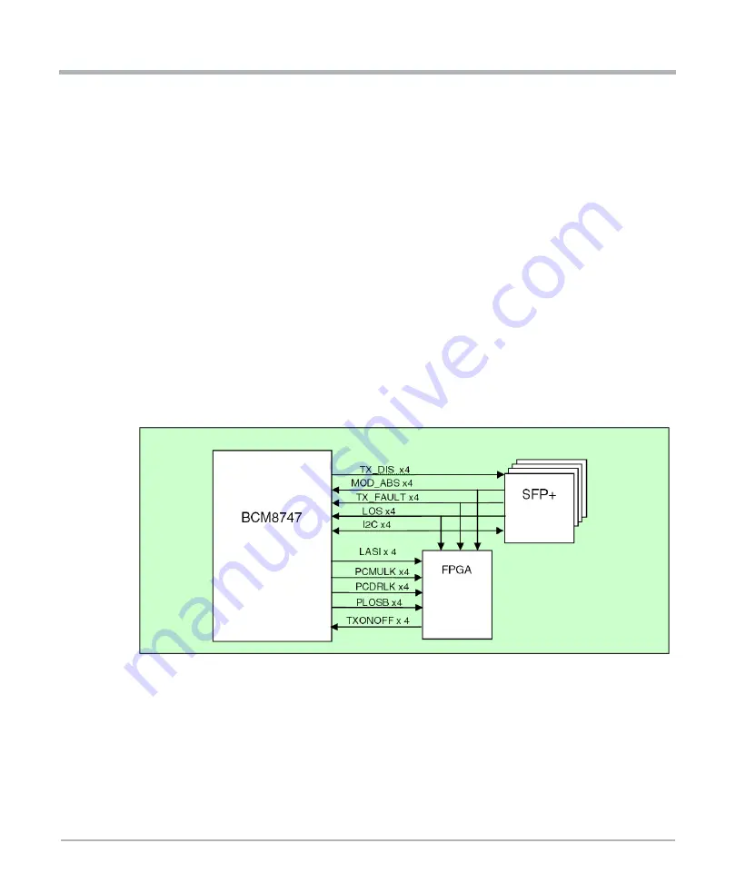
The ATCA-F125 provides four SFP+ module receptacles on the front panel, two for base
uplinks and two for fabric uplinks. The SFP+ signals LOS, TX_FAULT and MOD_ABS are
monitored for status by the BCM8747 PHY. Status changes will result in a service
processor interrupt.
Each SFP+ module's I2C signals are routed to the BCM8747 PHY which provides four
separate SFP+ I2C interfaces. The service processor uses these I2C interfaces, accessed
through the PHY management port, to read the module's on-board EEPROM information
to determine type and vendor specific information.
The individual TXONOFF signals on the BCM8747 are connected to the FPGA which
allows them to be driven under software control. This enables software to individually
enable and disable the SFP+ optical outputs.
The PCMULK, PCDRLK, PLOSB and LASI signals from each BCM8747 port are
connected to the FPGA to allow them to be monitored by software. The PLOSB and LASI
signals can also generate an interrupt to the service processor.
Figure 4-8 SFP+ Module Status and Control Interface
Содержание 6873M Artwork
Страница 1: ...ATCA F125 6873M Artwork Installation and Use P N 6806800J94N December 2019 ...
Страница 8: ...List of Figures 8 ATCA F125 6873M Artwork Installation and Use 6806800J94N ...
Страница 28: ...28 ATCA F125 6873M Artwork Installation and Use 6806800J94N Sicherheitshinweise Sicherheitshinweise ...
Страница 114: ...114 ATCA F125 6873M Artwork Installation and Use 6806800J94N Battery Exchange Battery Exchange ...
Страница 116: ...116 ATCA F125 6873M Artwork Installation and Use 6806800J94N Related Documentation Related Documentation ...
Страница 117: ...1 ...


