Functional Description
ATCA-F125 (6873M Artwork) Installation and Use (6806800J94N)
73
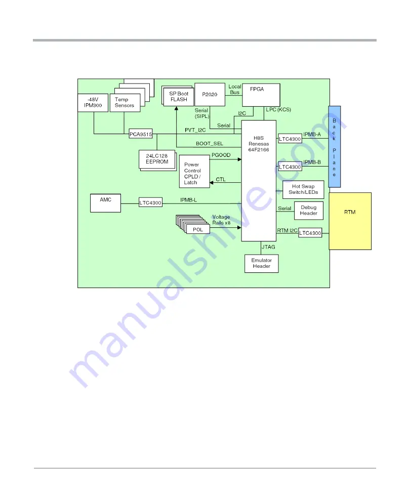
The ATCA-F125 board design supports a KCS LPC-based interface between the H8S
controller and the P2020 service processor. The H8S contains a native Low Pin Count
(LPC) interface. The P2020 does not have a LPC interface so a P2020 Local Bus to LPC
bus interface is implemented inside the FPGA.
Serial Port 2 of the H8S controller is routed to the on-board H8S debug header through an
RS-232 buffer to support device programming and the IPMC console interface. Refer to
Table 58 for the header pinout. This serial port will operate at 9600 baud rate.
The IPMC building block is designed to keep the payload running even during firmware
upgrade. When the payload is powered off, hot plug compatible buffers are used on signals
which bridge the management power domain and the payload power domain to prevent
leakage currents to the payload power domain. In case of an IPMC firmware upgrade, the
output signals to the payload remain unchanged. After IPMC firmware update is finished,
the IPMC reads status of the signals before driving them again.
Figure 4-2 IPMI Block Diagram
Содержание 6873M Artwork
Страница 1: ...ATCA F125 6873M Artwork Installation and Use P N 6806800J94N December 2019 ...
Страница 8: ...List of Figures 8 ATCA F125 6873M Artwork Installation and Use 6806800J94N ...
Страница 28: ...28 ATCA F125 6873M Artwork Installation and Use 6806800J94N Sicherheitshinweise Sicherheitshinweise ...
Страница 114: ...114 ATCA F125 6873M Artwork Installation and Use 6806800J94N Battery Exchange Battery Exchange ...
Страница 116: ...116 ATCA F125 6873M Artwork Installation and Use 6806800J94N Related Documentation Related Documentation ...
Страница 117: ...1 ...


