ATCA-F125 (6873M Artwork) Installation and Use (6806800J94N)
69
Chapter 4
Functional Description
4.1
Block Diagram
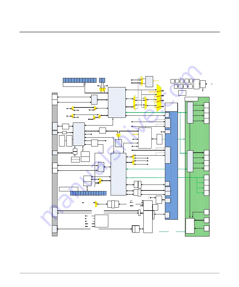
The following block diagram provides a high level functional view of the ATCA-F125 board
and its interfaces to the front panel, backplane, and RTM.
Figure 4-1 Block Diagram
%&>$@
%&>%@
IPMC
Backplane
=RQH&RQQHFWRUV
)&
%&
7R2WKHU
+XE
%RDUG
7R
6K0&V
7
7
8$57
,30%
%XVVHG
WR
6K0&V
%ODGHV
%URDGFRP
[*.;
[*;$8,
7R6HUYLFH
3URFHVVRU
*7
7&/.
&/.>@>$%@
%XVVHG
WR
%ODGH
6ORWV
%URDGFRP
%&0
[*;$8,
[*.;
3+<
6
3+<
7UDQV
IRUPHU
$0&%D\
6$7$
+''
6$7$
3RUW
3RUW
AMC Port 4-7
[3&,H
[3&,H
3
3URFHVVRU
56
[FYU
8$57
3RUW
8&>@
[*%;;$8,
%DFNSODQH=RQH&RQQHFWRUV
/RJLFDO6ORW
7R=RQH&RQQHFWRU
7R=RQH&RQQHFWRU
[*;$8,
%&0
[;$8,!
6),
6),
5-
*6*0,,
*6*0,,
%,;08;
7R=RQH&RQQHFWRU
&ORFN)3*$
6HPWHFK
7RS6\QF
0/9'6
2VFLOODWRU
0D[LP
)UDPHUV
[%,76668
7UDQV
IRUPHUV
0D[LP
)UDPHUV
7UDQV
IRUPHUV
[
5-
*6*0,,
*6*0,,
7RS6\QF%DVH
[*
;$8,
%&0
[;$8,!
6),
%,;
6)3
%,;
6)3
8&>@
3RUW
3RUW
*%;.;6(5'(6
%DVH;&RQQHFW
7[WR8&>@5[WR8&>@
%DVH;&RQQHFW
7[WR8&>@5[WR8&>@
*6*0,,
WR$0&3RUW
3RUW
*6*0,,
WR$0&3RUW
WR$0&3RUW
[*E(
0$&3+<
6
3&,([
*;$8,
$0&3RUW
$0&3RUW
[*;$8,
7R=RQH&RQQHFWRU
*;$8,
[*;$8,
7R=RQH&RQQHFWRU
',00
''5
Z(&&
6$7$
%ULGJH
[3&,H
[*6*0,,
%$6(.;
%DFNSODQH=RQH&RQQHFWRUV
[*7
/RJLFDO6ORW
7UDQVIRUPHUV
3+<V
[*6*0,,
*6*0,,
*6*0,,
$0&3RUW
7R=RQH
&RQQHFWRU
7R=RQH
&RQQHFWRU
$0& !%DVH;&RQQHFW
$0& !)DEULF;&RQQHFW
)DEULF !$0&;&RQQHFW
8&>@
)DEULF;&RQQHFW
7[WR8&>@5[WR8&>@
)DEULF;&RQQHFW
7[WR8&>@5[WR8&>@
$0& !)DEULF;&RQQHFW
)DEULF !$0&;&RQQHFW
$0& !%DVH;&RQQHFW
6$7$
*6*0,,
*6*0,,
[*6*0,,
7UDQV
IRUPHUV
*6*0,,
*6*0,,
8$57WR,30&
*6*0,,
%RRW.HUQHO
125)ODVK
/RFDO%XV
%RRW.HUQHO
125)ODVK
86%
3+<
)LOH6\VWHP
1$1')ODVK
[,QWHU6KHOI6\QFK
[
5-
0/9'6
0DVWHU6ODYH6\QFK
*367R'56
*36SXOVHSHUVHFRQG
63,WR3URFHVVRU
WR%DVH)DEULF
7RS6\QF%DVH
)URP=RQH&RQQHFWRU
%,;08;
%,;08;
5*0,,
6
*7
5-
0$*
+8%
86%
),;
6)3
),;
6)3
)URQW3DQHO
ARTM-F125
),;
6)3
),;
6)3
%&0
[;$8,!
6),
),;
6)3
),;
6)3
),;
6)3
),;
6)3
%,;
6)3
%,;
6)3
%,;
6)3
%,;
6)3
%,;
6)3
%,;
6)3
[*;$8,
[*;$8,
[*;$8,
[*6*0,,
6),
6),
6),
6),
6),
6),
6),
6),
6),
6),
6),
)3*$
%&0
[;$8,!
6),
',00
''5
Z(&&
&ORFN'LVWULEXWLRQ
0+=
0+]3&,(
0+]
0+]
0+]
,QSXW
3:5
0RGXOH
9'&
9
0RGXOH
9B0*7
9
9
9
9
9
9
9
9 9
+RW
6ZDS
-7$*
&RQWUROOHU
%
33
33
33
3
33
*(
*(
3
*(
*(
33
33
3
%
%
%
$
%
$
%
%
$
$
%
%
$
%
%
$
%
%
%
%
3
3
$
%
$
%
%
%,;08;
$
%
%
$
%
%
$
%
%
+*+*
3
3
33
3
3
+*
+*
3
3
3
3
$
$
%
%
%
%
%
$
%
%
$
$
$
%
%
%
%
6
5*0,,
8&>@
8&>@
6
3+<
7UDQV
IRUPHU
3+<
6*0,,
%
%DVH;
3
3
9
9
0+]
9
9
AMC Port 4-7
To Zone 3
Connector
(7+
(7+
(7+
(7+
(7+
(7+
(7+
(7+
(7+
(7+
(7+
(7+
(7+
(7+
(7+
(7+
(7+
&2162/(
86%
7(7(
06(;7
(;7(;7
(;7(;7
60$
0+]
60$
336
5-
7LPHRI'D\
72'
336
0+]
5*0,,
*6*0,,
7R=RQH&RQQHFWRU
Содержание 6873M Artwork
Страница 1: ...ATCA F125 6873M Artwork Installation and Use P N 6806800J94N December 2019 ...
Страница 8: ...List of Figures 8 ATCA F125 6873M Artwork Installation and Use 6806800J94N ...
Страница 28: ...28 ATCA F125 6873M Artwork Installation and Use 6806800J94N Sicherheitshinweise Sicherheitshinweise ...
Страница 114: ...114 ATCA F125 6873M Artwork Installation and Use 6806800J94N Battery Exchange Battery Exchange ...
Страница 116: ...116 ATCA F125 6873M Artwork Installation and Use 6806800J94N Related Documentation Related Documentation ...
Страница 117: ...1 ...


