background image

WB33-38-IA-IEN120940 | IME-WB3800 | Version 4.0

EN

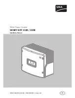
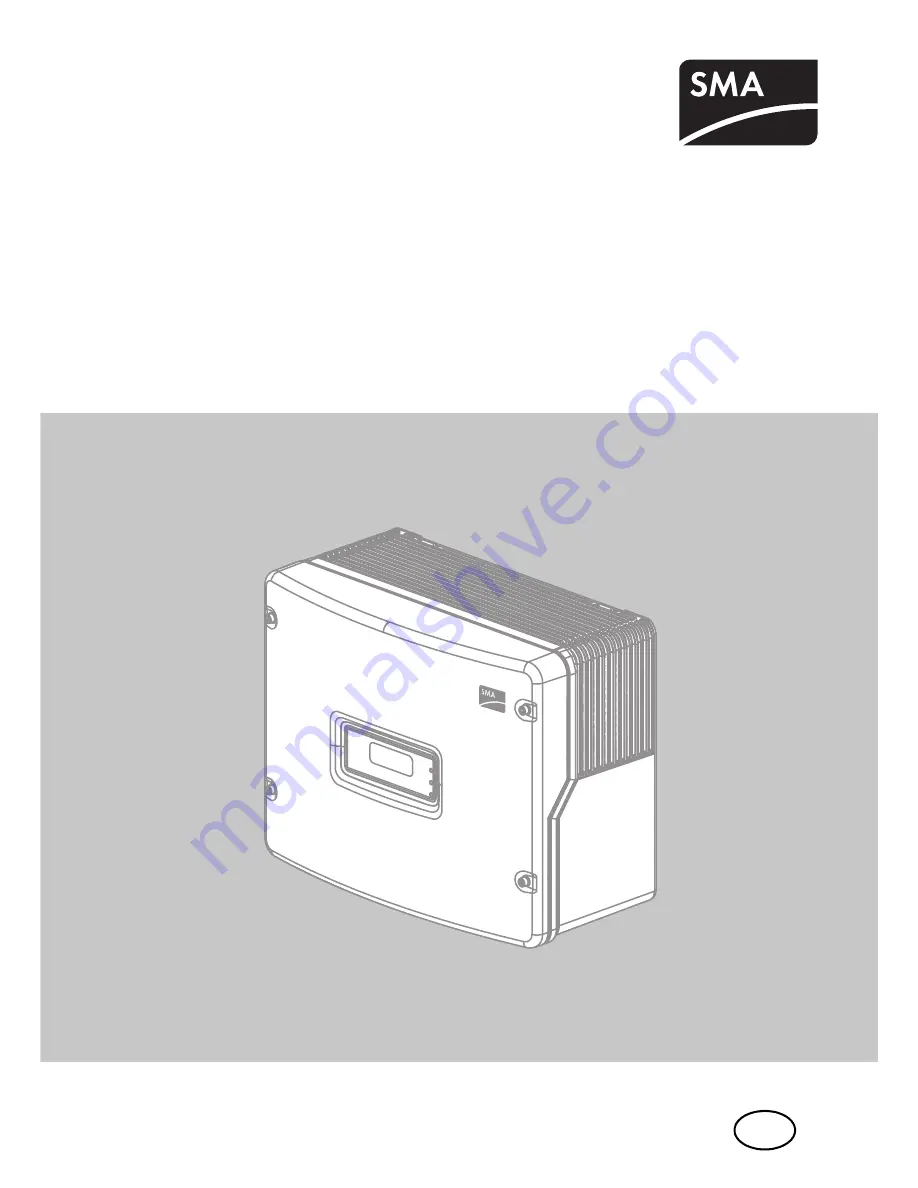
Wind Power Inverter

WINDY BOY 3300 / 3800

Installation Manual

Содержание WINDY BOY 3300

Страница 1: ...WB33 38 IA IEN120940 IME WB3800 Version 4 0 EN Wind Power Inverter WINDY BOY 3300 3800 Installation Manual...

Страница 2: ......

Страница 3: ...2 2 Safety Precautions 10 2 3 Explanation of Symbols 11 2 3 1 Symbols on the Inverter 11 2 3 2 Symbols on the Type Label 12 3 Unpacking 13 3 1 Scope of Delivery 13 3 2 Identifying the Inverter 14 4 As...

Страница 4: ...g DC Connectors 33 5 5 4 Connecting the Small Wind Turbine System DC 34 5 6 Communication 36 5 7 Setting the Grid and Country Parameters 36 5 7 1 Setting the Installation Country 36 5 7 2 Setting to S...

Страница 5: ...9 3 Red LED is Permanently On 62 9 3 1 Checking the Small Wind Turbine System for Earth Faults 62 9 3 2 Checking the Function of the Varistors 65 10 Decommissioning 67 10 1 Dismantling the Inverter 67...

Страница 6: ...Table of Contents SMA Solar Technology AG 6 WB33 38 IA IEN120940 Installation Manual 12 Accessories 76 13 Contact 77...

Страница 7: ...WB 3800 IT Please store this manual where it will be accessible at all times 1 2 Target Audience This manual is for the use of electrically skilled persons The tasks described in this manual may be p...

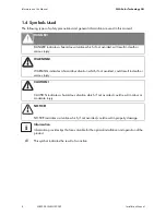
Страница 8: ...h or serious injury WARNING WARNING indicates a hazardous situation which if not avoided could result in death or serious injury CAUTION CAUTION indicates a hazardous situation which if not avoided co...

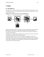
Страница 9: ...nts diesel generators etc The manufacturer of the small wind turbine system or generator must have approved his plant for operation with this Windy Boy For safety reasons it is not permitted to modify...

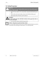
Страница 10: ...ly Work on the inverter should only be carried out as described in this manual All safety precautions listed here must be observed CAUTION Risk of burns through contact with the hot enclosure during o...

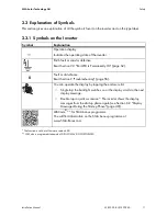
Страница 11: ...erating state of the inverter Earth fault or varistor defective Read Section 9 3 Red LED is Permanently On page 62 Fault or disturbance Read Section 9 Troubleshooting page 56 You can operate the displ...

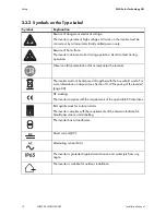
Страница 12: ...on that accompanies the inverter The inverter must not be disposed of together with the household waste For more information on disposal see Section 10 4 Disposing of the inverter page 68 CE marking T...

Страница 13: ...Inverter B 1 Wall mounting bracket C 2 Ventilation grid 1 x left 1 x right D 5 Filler plug for wall mounting sealing E 2 Cheese head screw M6 F 1 AC connection socket bush insert protective cap for bu...

Страница 14: ...ation Manual 3 2 Identifying the Inverter You can identify the inverter be means of the type label The type label is located on the right hand side of the enclosure On the type label you will find the...

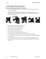
Страница 15: ...o not mount the inverter on flammable construction materials Do not mount the inverter in areas where highly flammable materials are stored Do not mount the inverter in a potentially explosive atmosph...

Страница 16: ...service friendliness Mount vertically or tilted backwards by max 45 Never mount the device with a forward tilt Never mount the device with a sideways tilt Do not mount in a horizontal position The con...

Страница 17: ...s or objects as shown in the diagram in order to guarantee adequate heat dissipation Multiple inverters installed in areas with high ambient temperatures If necessary increase the spacing between the...

Страница 18: ...es 2 Use filler plugs to fill any unused holes in the wall mounting bracket Insert the filler plugs into the wall mounting bracket from the outside the side that will later be placed against the wall...

Страница 19: ...ing suitable screws and washers 4 Hook the inverter by its top mounting plates into the wall mounting bracket with both attachments of the wall bracket passing through the cutouts on the inverter 5 Vi...

Страница 20: ...towards the enclosure Tighten the screw with a torque of approx 5 Nm 7 Check to ensure that the inverter is securely in place The wall mounting bracket is designed in such way that the inverter is ti...

Страница 21: ...e underside of the inverter For WB 3300 11 WB 3800 11 the inverter is fitted with 2 negative and 2 positive DC connectors NOTICE Electrostatic discharge can damage the inverter Internal components of...

Страница 22: ...0 11 WB 3800 11 the inverter is fitted with 2 negative and 2 positive DC connectors Object Description A Slot and connection area for communication B Jumper slot for fan test C Flat male tab for earth...

Страница 23: ...at www SMA de en The maximum cable lengths as a function of conductor cross section are shown in the following table Cable requirements Connection requirements of the network operator Always comply wi...

Страница 24: ...inverters to the same miniature circuit breaker Observe the maximum permissible fuse protection of the inverter when selecting the miniature circuit breaker DANGER Danger to life by fire When a gener...

Страница 25: ...SMA de en in the Technical Description category of the respective inverter 2 Disconnect the miniature circuit breaker and secure against accidental or inadvertent reconnection 3 If necessary replace...

Страница 26: ...rt the PE conductor green yellow into the screw terminal with the earth sign on the bush insert and tighten the screw The PE conductor must be longer than the connection wires N and L 10 Insert neutra...

Страница 27: ...ure screw acts as a seal and to relieve strain The AC connection socket is now assembled 15 Close the bush insert with the protective cap provided if the inverter is not to be connected immediately 16...

Страница 28: ...washer terminal lug with protective conductor and conical spring washer on cheese head screw The teeth of the conical spring washer must be facing the metal bracket 3 Insert the cheese head screw into...

Страница 29: ...lt settings For more information see the Technical Description Operating Parameters at www SMA de en Procedure 1 Open the inverter as described in Section 7 2 Opening the Inverter page 48 2 Set the sw...

Страница 30: ...V 20 A DANGER Risk of lethal electric shock or fire The maximum possible input current is limited by the connectors used If the connectors are overloaded an electric arc may occur thus causing a fire...

Страница 31: ...e small wind turbine system must be fitted with the supplied DC connectors Assemble the DC connectors as follows Ensure the connectors have the correct polarity The DC connectors are marked with the s...

Страница 32: ...er as described in Section 5 5 4 Connecting the Small Wind Turbine System DC page 34 Result What to do If the stranded wire is visible in the chamber of the clamping bracket the cable is correctly pos...

Страница 33: ...lease the DC connector To do so insert a screwdriver blade width 3 5 mm into the lateral catch and lever it open 3 Carefully pull the DC connector apart 4 Release the clamping bracket Do this by inser...

Страница 34: ...bine System DC 1 Connect the assembled DC connectors to the inverter The DC connectors click audibly into position To release the DC connectors see Section 7 2 Opening the Inverter page 48 DANGER Dang...

Страница 35: ...by moisture penetration The inverter is only properly sealed when all the unused DC inputs are closed with DC plug connectors and sealing plugs DO NOT insert the sealing plugs DIRECTLY into the DC inp...

Страница 36: ...inverter is available in the download area at www SMA de en in the category Technical Description of the respective inverter 5 7 1 Setting the Installation Country Using the Default parameter you can...

Страница 37: ...ways of setting the inverter to stand alone grid operation Setting via Sunny WebBox or Setting via Sunny Data Control or Sunny Explorer DANGER Danger to life due to high voltages in the event of elec...

Страница 38: ...d you can change the following parameters on the PC with the Windy Boy Setup Tool www SMA de en Vpv Start UdcWindStart Wind_a0 Wind_a3 Pmax P Wind Ramp KP Wind Reg KI Wind Reg T Stop A description of...

Страница 39: ...LEDs on or flashing the start up phase commences Green LED on commissioning successful or Green LED flashing grid connection conditions have not yet been reached Wait until the green LED is permanentl...

Страница 40: ...tap on the enclosure lid the inverter displays the firmware version of the internal processors After a further 5 seconds or another tap the inverter displays the configured country standard example VD...

Страница 41: ...he inverter on the AC side To do this you have to make the AC connection AC plug or direct connection and switch on the circuit breaker of the grid feed cable fuse or miniature circuit breaker 3 The i...

Страница 42: ...y and voltage monitoring As soon as the actual measured value exceeds the permitted range adjusted disconnection threshold the inverter disconnects from the electricity grid In this way the inverter d...

Страница 43: ...alibration value of the voltage limit applied is shown in the display of the inverter The voltage is increased step by step until the disconnection threshold is reached and the inverter disconnects fr...

Страница 44: ...requency limit applied is shown in the display of the inverter The frequency is reduced step by step until the disconnection threshold is reached and the inverter disconnects from the electricity grid...

Страница 45: ...alternates between the following values Disconnection value Calibration value Reaction time Current power frequency Once the inverter has carried out all four tests it switches to the Turbine Mode The...

Страница 46: ...rrent according to the generator voltage Characteristic Curve Operation After the start up procedure the inverter switches to characteristic curve operation and regulates the input current according t...

Страница 47: ...ath or serious burns Before opening the inverter observe the following Ensure that no voltage is present on the AC side Ensure that neither voltage nor current is present on the DC side NOTICE Electro...

Страница 48: ...the DC cables If current is present check the installation 4 Release and disconnect all DC connectors To do this insert a flat blade screwdriver blade width 3 5 mm into one of the side slots and pull...

Страница 49: ...he display have gone out 8 Loosen the screws of the enclosure lid 9 Slowly pull the enclosure lid forward and off The inverter is now open and de energised DANGER Danger to life due to high voltages i...

Страница 50: ...hem in To release the DC connectors see Section 7 2 Opening the Inverter page 48 The DC connectors click audibly into position To release the DC connectors see Section 7 2 Opening the Inverter page 48...

Страница 51: ...Manual WB33 38 IA IEN120940 51 5 Connect the AC plug 6 Switch on the miniature circuit breaker 7 Check whether the inverter display and LEDs indicate a normal operating state see Section 6 Commission...

Страница 52: ...be cleaned with a vacuum cleaner If you do not achieve satisfactory results with a vacuum cleaner dismantle the fans for cleaning Proceed as follows 1 Disconnect the inverter on both the DC and AC si...

Страница 53: ...8 2 2 Checking the Fans There are two ways to check whether the fan is working Set the Fan Test parameter to 1 in the installer mode using Sunny Data Control Sunny Explorer or Sunny WebBox or Plug the...

Страница 54: ...provided jumper in the slot on the system control board as shown below 3 Close the inverter as described in Section 7 3 Closing the Inverter page 50 4 Restart the inverter 5 Check the air flow of the...

Страница 55: ...t ventilation grid Insert your finger in the space between the ventilation grid and the upper part of the enclosure and remove the ventilation grid laterally 2 Clean the ventilation grid with a soft b...

Страница 56: ...tch at the freight forwarder within 24 hours and repair service 9 1 Blink Codes Green Red Yellow Status flashing flashing flashing OK start up phase permanently on off off OK feed in operation permane...

Страница 57: ...repeated disconnect the inverter again and contact the SMA Service Line ACVtgRPro The 10 minute average line voltage is no longer within the permissible range This can be caused by one of the followin...

Страница 58: ...eter with the SMA Service Line EEPROM Transitional disturbance while data is being written to or read from EEPROM The data has no relevance to safe operation This disturbance has no effect on the perf...

Страница 59: ...system Check the small wind turbine system for earth faults as described in Section 9 3 1 Checking the Small Wind Turbine System for Earth Faults page 62 ROM The inverter firmware is faulty Contact th...

Страница 60: ...perating parameters Vac Min and Vac Max If the line voltage is within the tolerance range yet Vac Bfr or Vac Srr faults are still displayed contact the SMA Service Line VpvMax Vpv Max Overvoltage at t...

Страница 61: ...the grid impedance and grid connection at the inverter Use an AC cable with an adequate cross section low impedance as described in Section 5 3 2 Connecting the Inverter to the Electricity Grid AC pag...

Страница 62: ...iberately earthed small wind turbine systems check from time to time that the varistors in the inverter are working properly since a varistor fault can no longer be displayed 9 3 1 Checking the Small...

Страница 63: ...he small wind turbine system and the earth potential Measure the resistance between L1 of the small wind turbine system and the earth potential Measure the resistance between L2 of the small wind turb...

Страница 64: ...0 Installation Manual The measured resistance is very small 10 There is an earth fault in the small wind turbine system Have the installer of the small wind turbine system eliminate the earth fault be...

Страница 65: ...ng the Inverter page 48 2 Use a multimeter to check that in each of the installed varistors there is a conductive connection between terminals B and C Position of the varistors The position of the var...

Страница 66: ...t of the varistors is now complete There is no conductive connection The respective varistor is defective and must be replaced Varistor failure is generally due to influences that affect all varistors...

Страница 67: ...Opening the Inverter page 48 2 Remove all cables from the inverter 3 Close the inverter with the 4 screws and the corresponding conical spring washers 4 Remove the ventilation grids on either side 5...

Страница 68: ...t and size of the inverter 10 3 Storing the Inverter Store the inverter in a dry place where ambient temperatures are always between 25 C and 60 C 10 4 Disposing of the inverter Dispose of the inverte...

Страница 69: ...mum DC power at cos 1 3 820 W Recommended generator power at 2 500 full load hours per year 3 100 W Recommended generator power at 5 000 full load hours per year 2 800 W Maximum input voltage 500 V DC...

Страница 70: ...t at 240 V 13 8 A Maximum output current 18 A Total harmonic factor of the output current at total harmonic factor of the AC voltage 2 and AC power 50 rated power 3 Rated power frequency 50 Hz AC powe...

Страница 71: ...t cos 1 4 040 W Recommended generator power at 2 500 full load hours per year 3 600 W Recommended generator power at 5 000 full load hours per year 3 300 W Maximum input voltage 500 V DC voltage range...

Страница 72: ...rrent at 240 V 15 8 A Maximum output current 18 A Total harmonic factor of the output current at total harmonic factor of the AC voltage 2 and AC power 50 rated power 3 Rated power frequency 50 Hz AC...

Страница 73: ...ission typical 42 dB A Power loss in night operation 0 10 W Topology LF transformer Cooling concept OptiCool temperature controlled fan Fan connection designed for safe disconnection in accordance wit...

Страница 74: ...ndard as per 12 2011 WB 3300 WB 3300 IT WB 3300 11 WB 3800 WB 3800 IT WB 3800 11 VDE0126 1 1 VDE AR N 4105 VDE0126 1 1 UTE C15 712 1 UTE C15 712 1 EDF SEI req DK5940 PPC RD 1663 2000 RD 661 2007 AS 47...

Страница 75: ...Enclosure lid screws 6 0 Nm Additional earthing screw 6 0 Nm Cheese head screw for attaching enclosure to wall mounting bracket 6 0 Nm SUNCLIX swivel nut 2 0 Nm RS485 communication connection 1 5 Nm I...

Страница 76: ...voltage protection for small wind turbine systems with Windy Boy WBP Box 500 Ventilation grid Ventilation grid set right and left as spare parts 45 7202 Replacement varistors Set of thermally controll...

Страница 77: ...er to provide you with the necessary assistance Inverter type Inverter serial number Type of connected small wind turbine system Optional equipment e g communication products Blink code or display mes...

Страница 78: ......

Страница 79: ...nditions come enclosed with your device These are also available online at www SMA de and can be downloaded or are available on paper from the usual sales channels if required Trademarks All trademark...

Страница 80: ...USBMJB 1UZ UE XXX 4 VTUSBMJB DPN BV 4 FOFMVY 413 XXX 4 FOFMVY DPN 4 FJKJOH PNNFSDJBM P UE XXX 4 IJOB DPN 4 FDI 3FQVCMJD T S P XXX 4 FDI DPN 4 SBODF 4 4 XXX 4 SBODF DPN 4 FMMBT XXX 4 FMMBT DPN 4 C SJDB...

Отзывы: