Commissioning
SMA Solar Technology AG
46
WB33-38-IA-IEN120940
Installation Manual
6.4 Operating States of the Inverter
Start-Up Procedure
Providing that the inverter is supplied with sufficient voltage and power, the three LEDs on the inverter
light up simultaneously, indicating that the start-up process is ongoing.
As soon as the DC input voltage reaches the value configured for the parameter "Vpv-Start", the
inverter triggers several self-tests, measuring procedures and synchronization with the electricity grid.
This operating state is indicated on the inverter by the flashing green LED.
Once the DC input voltage has reached the "Vpv-Start" value for the time configured in "T-Start" and
all the tests have been completed successfully, the inverter connects to the electricity grid and the
green LED comes on permanently. The inverter then switches to characteristic-curve operation, and
regulates the input current according to the generator voltage.
Characteristic-Curve Operation
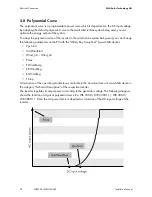
After the start-up procedure, the inverter switches to characteristic-curve operation and regulates the
input current according to the generator voltage.
The inverter then begins to exert a load on the small wind turbine system, draws power from the system
according to the input voltage present, and then feeds it into the electricity grid. The maximum power
output corresponds to the maximum AC power of the inverter. However, this can be reduced via the
"Pmax" parameter.
Shutdown Procedure
If wind strength is so low that the DC input voltage falls below an internally calculated value, the
inverter stops feeding energy to the electricity grid for the period defined in "T-Stop". As soon as DC
input voltage increases again, the inverter switches back to characteristic-curve operation.
If the DC input voltage remains below an internally calculated value for the time set in "T-Stop", the
inverter will switch off.
If the DC input voltage is no longer sufficient to supply the on-board electronics with power, the
inverter switches off immediately.


