background image

SMA America, LLC

6  Electrical Connection

Technical description

SI4548_6048-US-TB_en-13

55

6.4.4  Multifunction Relay 1 and 2

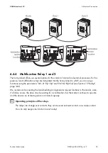
The Sunny Island offers you several options for the control of internal and external processes. For this 
purpose, two multifunction relays are integrated into the Sunny Island to which you can assign 
functions using the parameters "241.01 Rly1Op" and "241.02 Rly2Op" (see Section 15 "Relays", 
page 140).
We recommend connecting the load shedding and generator request functions to the master, since, 
if a failure occurs, the slave may be waiting for a confirmation, but the master continues to operate 
and the device can at least operate in a limited capacity.

Operating principles of the relays

The relays are change-over contacts; they can be used as break contact or as make contact.
You can only assign one function to each relay!

Содержание Sunny Island 4548-US

Страница 1: ...SI4548_6048 US TB_en 13 Version 1 3 US Off Grid Inverter SUNNY ISLAND 4548 US 6048 US Technical description...

Страница 2: ......

Страница 3: ...s shall be liable for any indirect incidental or consequential damages under any circumstances The exclusion of implied warranties may not apply in all cases under some statutes and thus the above exc...

Страница 4: ...equipment or personnel It calls attention to a procedure or practice which if not correctly performed or adhered to could result in damage to or destruction of part or all of the SMA equipment and or...

Страница 5: ...duct has large electrical potential differences between its conductors Arc flashes can occur through air when high voltage current flows Do not work on the product during operation Observe the operati...

Страница 6: ...st conform with the laws regulations codes and standards applicable in the jurisdiction of installation SMA assumes no responsibility for the compliance or non compliance with such laws or codes in co...

Страница 7: ...cautions 26 3 1 Important Information on Operation 26 3 2 Potential Hazards 27 4 Assembly 28 4 1 Selecting the Mounting Location 28 4 2 Mounting the Sunny Island with the Wall Mounting Bracket 31 4 2...

Страница 8: ...nput 59 6 5 Interface for External Communication 60 6 5 1 Connection of the Interface for External Communication 60 7 Control Elements 64 7 1 Display Messages 65 7 2 DC Circuit Breaker 65 7 3 Buttons...

Страница 9: ...Data on an SD Card 93 11 1 Inserting the SD Card 96 11 2 Removing the SD Card 97 11 3 Saving and Loading Parameters 97 11 4 Writing Log Data 97 11 5 Status Messages 98 11 6 Updating the Firmware 99 1...

Страница 10: ...External Sources 116 14 1 Generator 116 14 1 1 Parallel Connection 116 14 1 2 Generator Start Options 118 14 1 3 Generator Operation 120 14 1 4 Manual Generator Operation 121 14 1 5 Automatic Generat...

Страница 11: ...cluster System On and Off 146 16 3 1 Activation Startup 146 16 3 2 Stopping and Switching Off 146 16 3 3 Load Shedding in a Multicluster System 147 16 4 Generator Operation 147 16 5 Behavior with Diff...

Страница 12: ...ontroller 140 not UL certified 164 19 2 Adjustable Parameters 166 19 2 1 Inverter Settings 210 166 19 2 2 Battery Settings 220 167 19 2 3 External Settings 230 171 19 2 4 Relay Settings 240 180 19 2 5...

Страница 13: ...20 6 3 Category GEN 207 20 6 4 GRD Category 207 20 6 5 Category REL 208 20 6 6 Category SYS 209 20 7 Failure Categories 209 20 8 Warnings and Error Messages 210 20 8 1 Category INV 210 20 8 2 Categor...

Страница 14: ......

Страница 15: ...e device and has demonstrable practical experience of mounting connecting and commissioning of the device An electrically qualified person is trained to deal with the dangers and hazards involved in i...

Страница 16: ...aving manner The utility grid can also be integrated The Sunny Island can also deactivate loads automatically if the battery does not provide sufficient electrical energy The critical component of the...

Страница 17: ...one grid operation The Sunny Island also has an integrated anti islanding feature which stops the production of electricity when the grid goes down If this process is tripped the system also completel...

Страница 18: ...2 Sunny Island 4548 US 6048 US SMA America LLC 18 SI4548_6048 US TB_en 13 Technical description Components of a Sunny Island System...

Страница 19: ...US TB_en 13 19 Single Phase System 120 Vac up to 6 kW 4 5 kW with SI 4548 US 10 6 kW with SI 6048 US 10 Single Phase Parallel System 120 Vac up to 18 kW Maximum three Sunny Island inverters of the typ...

Страница 20: ...System 240 Vac up to 12 kW Two Sunny Island inverters of the types SI 4548 US 10 5048U 6048 US 10 You can combine the various types in any order Three Phase System 120 208 Vac up to 18 kW Three Sunny...

Страница 21: ...6048 US 10 Within one phase only Sunny Island inverters of the same type may be used Different types may be connected to L1 and L2 e g L1 with 2 x SI 4548 US 10 and L2 with 2 x SI 6048 US 10 SMA Multi...

Страница 22: ...Island 4548 US 6048 US SMA America LLC 22 SI4548_6048 US TB_en 13 Technical description 2 2 At a Glance The following figure provides an overview of all control elements and connections of the Sunny...

Страница 23: ...ard E Opening for the additional connections area insertion of the cables via conduits F Connection area for additional connections G Opening for the additional connections area insertion of the cable...

Страница 24: ...1 Rubber plugs for feed through of one cable K 2 Rubber plugs for feed through of two cables L 1 SD card M 2 M6x10 hexagon socket screw and split lock washers for connecting the Sunny Island to the wa...

Страница 25: ...od fastener 3 8 in or 10 mm Flat blade screwdriver 3 32 in 2 5 mm Flat blade screwdriver SZS 1 0 x 6 5 Allen key 1 8 in to 5 16 in 3 mm to 8 mm Multimeter Open end box wrenches or socket wrenches in t...

Страница 26: ...to parallel connection of Sunny Island inverters which are set to different grid voltages Do not connect a Sunny Island in parallel if its line voltage is set to different values Batteries may be dest...

Страница 27: ...one grid Risk of death or serious injury due to electric shock The Sunny Island can start on its own Before working on the stand alone grid disconnect all sources of AC and DC power Danger to life if...

Страница 28: ...ched inadvertently Risk of injury due to the Sunny Island falling during transport or mounting Physical injury fractures or crushing and damage to the Sunny Island Consider the weight of the Sunny Isl...

Страница 29: ...oid power reduction due to excessive heating Mount the Sunny Island in such a way that the display is at eye level in order to allow the operating state to be read at all times Mount vertically or til...

Страница 30: ...ilation when installing the Sunny Island a minimum clearance of 12 in 30 cm at the sides and top must be maintained Operation and reading are made easier by installing the Sunny Island with its displa...

Страница 31: ...SMA America LLC 4 Assembly Technical description SI4548_6048 US TB_en 13 31 4 2 Mounting the Sunny Island with the Wall Mounting Bracket...

Страница 32: ...ng location 3 Drill holes on the markings for them 4 Secure the wall mounting bracket to the wall using appropriate screws and washers Tighten the screws in a clockwise direction Risk of injury due to...

Страница 33: ...unting bracket on both sides using the screws M6x10 provided Tighten the screws clockwise 7 Ensure that the device is securely in place 8 Close the recessed grips with the ventilation grids provided T...

Страница 34: ...of 2 in 50 mm If two or more Sunny Island inverters have to be installed mount the inverters on two studs each in order to get better cooling Make sure that the wall where you intend to install the S...

Страница 35: ...Sunny Island Standby page 74 2 Disconnect the Sunny Island from voltage sources see Section 9 4 Disconnecting the Device from Voltage Sources page 75 3 Ensure that the system cannot be accidentally s...

Страница 36: ...sequence depicted on the right Tighten the screws to a torque of 53 in lbs 6 Nm 2 Commission the Sunny Island as described in Section see Section 9 1 Switching On page 73 The Sunny Island is closed an...

Страница 37: ...ure and also serve as a strain relief of the cables at the connection Close all unused openings in the enclosure using the appropriate filler plugs Use the provided terminal blocks to connect the cabl...

Страница 38: ...ure Sensor see Section 6 4 1 Battery Temperature Sensor page 50 Battery Current Sensor see Section 6 4 2 Battery Current Sensor page 52 Communication for Multi Device Connection see Section 6 4 3 Comm...

Страница 39: ...a connection between N and PE is required for correct operation this must be done outside of the Sunny Island Before commissioning connect the Sunny Island 4548 US 6048 US and all other devices of the...

Страница 40: ...ding and tighten the fastening screw to a torque of 21 ft lbs 28 Nm Use an Allen key of 5 16 in 8 mm The grounding conductor is connected Calculating the Cross Section of a Grounding Conductor SMA can...

Страница 41: ...and and the battery and or DC device Danger to life due to chemical burns in the event of leaking acid Acid can escape in the event of improper handling of the battery Observe all safety indications a...

Страница 42: ...e drop associated with different cable cross sections Example For a 33 ft 10 m distance between the Sunny Island and the battery at least 66 ft 20 m of line is needed distance there and back Using a c...

Страница 43: ...Connection 1 Pull the positive DC cable through the conduit from the distribution board into the enclosure of the Sunny Island 2 Pull the negative DC cable through the conduit from the distribution b...

Страница 44: ...d tighten the fastening screw to a torque of 21 ft lbs 28 Nm Use an Allen key of 5 16 in 8 mm DC connection area The areas between the stripped line and the connection area must be clean This ensures...

Страница 45: ...g the sub distribution with circuit breakers The sub distribution must be equipped with appropriate circuit breakers Observe all locally applicable standards and directives Maximum permissible input c...

Страница 46: ...parallel connected devices Distributing loads and AC feed in generators in multiple phase systems Distribute the feed in power and the consumed power of the loads and AC feed in generators as equally...

Страница 47: ...ny Island 4 Remove the protective insulation of the three conductors isolation stripping length 3 4 in 18 mm 5 Insert PE into the terminal labeled AC1 Loads Sunny Boys and tighten the fastening screw...

Страница 48: ...uble split phase system In a double split phase system connect the master and slave 2 to line conductor L1 In a double split phase system connect slave 1 and slave 3 to line conductor L2 Three phase s...

Страница 49: ...rd through the conduit into the Sunny Island 4 Remove the protective insulation of the three conductors isolation stripping length 3 4 in 18 mm 5 Insert PE into the terminal labeled AC2 Gen Grid and t...

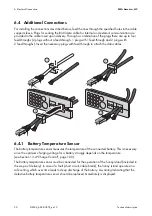
Страница 50: ...hroughs Insert the necessary plugs with feed through to attach the data cables 6 4 1 Battery Temperature Sensor The battery temperature sensor measures the temperature of the connected battery This is...

Страница 51: ...rature sensor to the outside of one of the battery cells Choose a spot between two cells and in the central area of the battery storage system The heat generation during operation is the greatest ther...

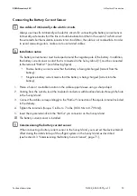
Страница 52: ...DC generators and DC loads in your off grid system Only one battery current sensor is necessary in a cluster this is to be connected to the cluster master Example Destruction of the battery due to th...

Страница 53: ...Intrinsically safe means that the line is double insulated and that in the event of a short circuit the wire melts but the insulation remains intact In addition the cable is not combustible In order...

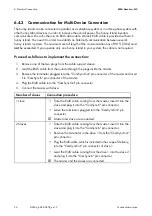
Страница 54: ...leeve 2 Lead the RJ45 cable from the outside through the plugs inside the master 3 Remove the terminator plugged into the ComSyncOut pin connector of the master and insert it in ComSyncIn pin connecto...

Страница 55: ...n functions using the parameters 241 01 Rly1Op and 241 02 Rly2Op see Section 15 Relays page 140 We recommend connecting the load shedding and generator request functions to the master since if a failu...

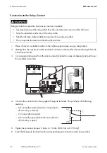
Страница 56: ...three pole terminals The pins have the following meaning NC normally closed when the Sunny Island is off the relay is closed C Contact front contact NO normally opened when the Sunny Island is off th...

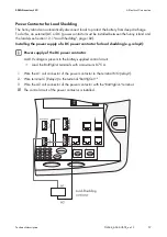
Страница 57: ...on 12 1 Load Shedding page 102 Installing the power supply of a DC power contactor for load shedding e g relay2 1 Wire the A1 coil connector of the power contactor to the terminal NO relay2 2 Wire ter...

Страница 58: ...eshold is at over 0 75 A This connection can be used for example to supply a DC contactor for load shedding Connecting the BatVtgOut Voltage Supply 1 Pierce a hole at a suitable location in the cable...

Страница 59: ...nsulated conductors with bootlace ferrules through the hole in the Sunny Island 3 Connect the cables correspondingly to the DigIn connection of the 4 pole terminal 4 Tighten the terminal screws torque...

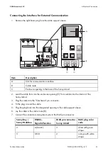
Страница 60: ...Communication via Powerline Powerline modem NLM is not possible in off grid systems Communication in a cluster Fitting a communication interface in a cluster is only necessary on the master Destructi...

Страница 61: ...e ComSmaIn pin connector 4 Fit the plug around the cable 5 Plug the plug back into the designated opening in the cable support sleeve 6 Lay the cable in the cable route B 7 Connect the conductors Assi...

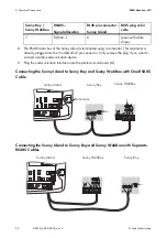
Страница 62: ...ation device 9 Plug the communication interface onto the printed circuit board A Connecting the Sunny Island to Sunny Boy and Sunny WebBox with One RS485 Cable Connecting the Sunny Island to Sunny Boy...

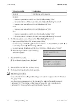
Страница 63: ...nsmission Speed The Sunny Island can be operated at different data transmission rates to communicate with external devices For this set the 250 06 ComBaud parameter Setting the baud rate If PV inverte...

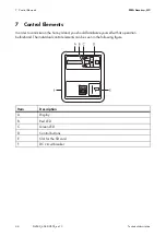
Страница 64: ...l Elements In order to commission the Sunny Island you should familiarize yourself with its operation beforehand The individual control elements can be seen in the following figure Item Description A...

Страница 65: ...Switching On and Off page 73 Meaning of the symbols Observe the information on the meaning of the individual symbols see Section 10 6 Display Messages Overview page 88 Item Description A Output power...

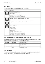
Страница 66: ...an SD card which can be used for updating firmware and as a service interface see Section 11 Archiving Data on an SD Card page 93 Button Function cancels the selected function answers NO navigates one...

Страница 67: ...begin with point 1 Check the connections Before commissioning check all electrical connections for correct polarity Ensure that all electrical connections are connected in accordance with the specific...

Страница 68: ...rameters only You cannot change general parameters using New Battery Emerg Charge if you would like to charge a deeply discharged battery using an external source 3 At New System set the following par...

Страница 69: ...ee Sunny Island 1Phase1 Single phase system one Sunny Island 1Phase2 Single phase system two Sunny Island 1Phase3 Single phase system three Sunny Island 2Phase2 Split phase system two Sunny Island 2Ph...

Страница 70: ...42 V to 52 V in 2 V steps for FLA and VRLA 43 2 V to 48 V in 1 2 V steps for NiCd default setting 48 0 V Nominal capacity of the battery 100 Ah to 10000 Ah default setting 100 Ah After entering all p...

Страница 71: ...1 BatCurSnsTyp None 50 mV 60 mV Only after activation of the parameter with 50 mV or 60 mV other parameters 02 03 and 04 in the menu 225 Battery Current Sensor will be shown and activated 5 Set the no...

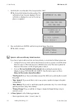
Страница 72: ...Cur to terminal 2 9 Start the Sunny Island see Section 9 1 Switching On page 73 10 Check the current direction 120 06 TotBatCur Current direction Discharging the battery No generator grid connected Lo...

Страница 73: ...notification is displayed as soon as the start up phase is completed 3 To change settings in the QCG manually start the QCG Press and hold down ENTER until the Sunny Island beeps three times The QCG...

Страница 74: ...is started 5 Press ENTER on the master A signal sounds The Sunny Island is in operation and the green LED is on 9 2 Stopping the Sunny Island Standby Proceed as follows to stop the Sunny Island 1 Pre...

Страница 75: ...ted from voltage sources 5 Wait at least 15 minutes to let the capacitors discharge and to allow the voltage inside the Sunny Island to drop to a safe level The Sunny Island is free of voltage 9 5 Rea...

Страница 76: ...itors Wait at least 15 minutes before restarting the Sunny Island The Sunny Island capacitors discharge during this time Switching on the DC circuit breaker If in rare cases the device cannot be switc...

Страница 77: ...menu level up Faster access to menus If you would like to access sub menu 7 navigate backwards from 1 over 9 instead of six steps forwards Switching to the Home Screen in case of inactivity If you do...

Страница 78: ...ct Access The main menus are divided into several sub menus In a sub menu you can select a second sub menu or a parameter You can access the navigation area from one of two levels User level Installer...

Страница 79: ...SMA America LLC 10 Operation Technical description SI4548_6048 US TB_en 13 79 Overview of the Menu Structure...

Страница 80: ...ettings Grid Generator 240 Relay Settings Relays 250 System Settings System 280 Password Setting Password entry 300 Diagnosis The following sub menus allow you to view system data 310 Inverter Diagnos...

Страница 81: ...cations The Sunny Island displays a corresponding message for parameters that can only be changed in standby mode or require a different password level Increments speed The increment size speed of the...

Страница 82: ...150 Compact Meters menu is intended primarily to help the installer commission the device The display gives you information at a glance on the following areas Battery 1 Battery 2 Inverter AC values I...

Страница 83: ...meter B Present battery state of charge BatSoc C Estimated error of the state of charge BatSocErr D Total battery current of the cluster TotBatCur E Battery temperature BatTmp Item Description A Name...

Страница 84: ...tion A Name of the compact meter B Present voltage at the inverter InvVtg C Present frequency at the inverter InvFrq D Present active power of the inverter InvPwrAt E Present reactive power at the inv...

Страница 85: ...iption A Name of the compact meter B Voltage of the external source ExtVtg C Frequency of the external source ExtFrq D Active power of the external source ExtPwrAt E Reactive power of the external sou...

Страница 86: ...ers endangers operational safety Damage to the off grid system and its components All parameter settings which could affect the operating safety of the off grid system are protected by the installer p...

Страница 87: ...1 2 3 4 5 6 21 7 Enter the password by pressing the up down arrow buttons 8 Confirm the password by pressing ENTER The installer password has been entered Operating level 1 the installer level is set...

Страница 88: ...parameter name and parameter value in 3 second intervals Bar display for output power or charging power the direction of energy flow is displayed by the arrows in the lower line Total active power of...

Страница 89: ...re is no generator connected no generator values are displayed Messages on the slave devices On the slave devices the upper line of the display shows the bar graph for output power or charging power T...

Страница 90: ...arge Cycle request reason The generator was requested via the generator operation s time dependent repetition cycle Parameter 235 17 GnTmOpCyc This symbol can only be shown in Multicluster operation E...

Страница 91: ...e within the set limits and that the generator was requested as a result of the battery state of charge Stopping the generator manually If the generator has been manually stopped no generator status i...

Страница 92: ...lures The Sunny Island can display a list of errors and warnings The serial number quantity of the error is on the upper line the time and date display changes in two second intervals On the lower lin...

Страница 93: ...xample M1111LOG DAT 8 3 is the old MS DOS format with a file name that has a maximum of 8 figures before and 3 figures after the dot Type of memory card SMA recommends the use of a Transcend SD card I...

Страница 94: ...m log failhisN log for SlaveN Failure history of the device saved by means of parameter 550 03 CardFunc option StoFailHis si030607 evt Event failure history for the day Format MMDDYY si030607 log Data...

Страница 95: ...System External source Loads The data saved on the SD card can be processed using common table calculation programs The first 13 lines of the file are used for information file header The following da...

Страница 96: ...the SD card can take several minutes During this time the buttons are disabled and cannot be used for making entries and three points appear in the lower line of the display If the procedure was succ...

Страница 97: ...parameters you have the following options Set1 load parameter set 1 Set2 load parameter set 2 Factory load the default settings reset 11 4 Writing Log Data Using the 550 04 DatLogEna parameter you ca...

Страница 98: ...SD card Display Description The SD card is deactivated The SD card is activated The memory capacity of your SD card has been exceeded The SD card has an invalid file format The SD card is not compati...

Страница 99: ...The update for single phase systems takes approximately five minutes For system configurations with more than one Sunny Island the software update can take up to 20 minutes A status bar shows the prog...

Страница 100: ...the slave and makes sure that all Sunny Island inverters within a system operate with the identical firmware version While the master updates the slaves the devices show the following messages among o...

Страница 101: ...rts Master The slave update is running Master The master update is completed Slave The slave update is completed Parameters and settings Individual parameters and settings are retained during a firmwa...

Страница 102: ...e the Sunny Island can carry out an automatic restart after the automatic shutdown After the automatic restart the generators connected to the Sunny Island can also charge the battery You can prevent...

Страница 103: ...ues can be defined with different priorities Define the time intervals t1 and t2 Starting time t1 with the 242 05 Lod1Tm1Str parameter set the start time for t1 and with it the end of t2 Starting time...

Страница 104: ...48 US supplies a power of 5 300 W for 30 minutes at 77 F 25 C and the Sunny Island 6048 US a power of 7 000 W Both Sunny Island inverters can deliver a power of 7 200 W for five minutes at 77 F 25 C T...

Страница 105: ...controlled way Activate the time controlled standby using the parameter 250 13 SlpAtNgt Set the parameter to Enable After activation set the start time and the stop time for standby Carry out the sett...

Страница 106: ...cells for every 2 V with lead acid batteries FLA and VRLA and 45 6 V 38 cells for every 1 2 V with nickel cadmium batteries FLA Flooded Lead Acid Closed lead acid batteries with liquid electrolyte in...

Страница 107: ...s a very precise internal state of charge calculation display value 120 01 BatSoc The procedure for calculating the state of charge is based on balancing the ampere hours This means that all currents...

Страница 108: ...The battery state of health display value 320 01 Soh is a measurement of the present useable capacity expressed as a percentage relative to the nominal capacity 100 means that the entire nominal capac...

Страница 109: ...ase the battery voltage increases as the battery is charged Once the battery voltage reaches the predefined value for the second phase Uo 222 07 to 222 09 ChrgVtgBoost or ChrgVtgFul or ChrgVtgEqu para...

Страница 110: ...float charge into silent mode The charging capability of batteries is highly dependent on the battery temperature For temperatures 77 F 25 C the charging voltage must be slightly increased and for te...

Страница 111: ...hroughput is reached when the sum of the discharge currents corresponds to the nominal capacity of the battery Example The battery has a nominal capacity of 100 Ah A nominal charge throughput is reach...

Страница 112: ...gSelMan activates the manual equalization charge on the Sunny Island If a generator is connected to the system it is automatically started and stopped once the equalization charge is completed Change...

Страница 113: ...ny Island has a sophisticated battery preservation mode The battery preservation mode prevents deep discharge from the battery as far as possible when the energy supply is low thus preventing a total...

Страница 114: ...eresis of 5 of the state of charge is provided Only battery preservation mode of level 3 is not automatically exited if an external voltage source grid reconnection generator start is present The batt...

Страница 115: ...is 300 page 193 13 7 Battery Lead Resistance In menu 221 Battery Property you can specify the battery lead resistance BatWirRes The resistance is the ohmic resistance from the battery to the input of...

Страница 116: ...grid specific and settings or values EXT common to both grid and generator 14 1 Generator The Sunny Island can start or stop a generator depending on load power or battery state of charge In this case...

Страница 117: ...enerator Sunny Island in the split phase system to a 240 V generator Generally the internal transfer relays of the slaves close only if the internal relay of the master is closed Plants with master an...

Страница 118: ...Sunny Island does not have the option of starting the generator It only monitors the generator input AC2 If while monitoring the input the device detects that the generator voltage and frequency are w...

Страница 119: ...e a bulb If no request is pending the signal is reset If an internal request is sent while the generator is already running the signal is disabled until the generator is externally stopped and the sto...

Страница 120: ...externally stopped this is detected the generator is disconnected and the stand alone grid is continued to be supplied 14 1 3 Generator Operation The Sunny Island allows automatic operation depending...

Страница 121: ...ode the generator is automatically started due to the settings This includes the start via the state of charge or the load power or by the request for a manual equalization charge 520 01 ChrgSelMan St...

Страница 122: ...nd of t1 is defined using GnTm2Str 1 Manual generator start 2 Generator is running detected beginning of warm up phase 3 Warm up phase completed 4 Generator is connected 5 Generator current limit 6 Cu...

Страница 123: ...he generator can be requested for support This function can be switched on or off default using the 235 09 GnPwrEna parameter The function is only effective if the 235 01 GnAutoEna parameter is simult...

Страница 124: ...nd 2 Manual generator start 3 Generator is running detected beginning of warm up phase 4 Warm up phase is completed connection 5 Generator current limit 6 Minimum run time has expired 7 Current is red...

Страница 125: ...rget value it is also reduced absorption phase see Section 13 4 Charge Control page 109 If the 234 15 GnCtlMod parameter is set to CurFrq the generator is also limited at frequencies lower than the no...

Страница 126: ...wer down phase is completed after the 234 10 GnCoolTm time the generator is stopped If a generator fault e g generator failure is detected the generator is also disconnected and then stopped immediate...

Страница 127: ...generators Sunny Boy If the generator is now manually started for example the frequency would be lowered if required as the Sunny Island synchronizes with the generator The AC feeding in generators S...

Страница 128: ...ric shock through residual voltage in the off grid system due to generator shut off delays Death or serious injuries The power down times depend on the generator type During the power down time there...

Страница 129: ...e see Section 12 9 Behavior in the Event of a Failure in a Three Phase System page 105 14 2 Grid The Sunny Island supports the operation of grid backup systems Here a distinction is made between two m...

Страница 130: ...ckup Operation and Anti Islanding In general Sunny Boy inverters in backup systems are working for feeding energy into the utility grid According to UL1741 an Anti Islanding has to be active During no...

Страница 131: ...ration the grid monitoring checks whether the permissible limits for voltage and frequency see Grid Reconnection are exceeded or grid failure for taking over supply the stand alone grid system For thi...

Страница 132: ...the parameters mentioned above These two time periods are subdivided via the following parameters 233 05 GdTm1Str 233 06 GdTm2Str The Sunny Island charges its batteries using the battery charging proc...

Страница 133: ...lled using the 232 08 GdMod parameter The cross section of the lines to the utility grid must be appropriate for the maximum current This ensures that the Sunny Island can feed into the utility grid w...

Страница 134: ...4 2 5 Grid Reconnection page 131 or the utility grid being disconnected In this case the time limits are relevant smaller deviations are permitted for longer than large deviations see Section 14 2 1 L...

Страница 135: ...Device Failure If a slave fails the system continues to operate using the remaining devices of the cluster 14 2 9 Limits and Power Control The Sunny Island burdens the grid at each line conductor wit...

Страница 136: ...as the Sunny Island is synchronized with the grid The AC feed in generators would then feed additional energy into the system and possibly overload the batteries In order to prevent this in this case...

Страница 137: ...stallation as follows The requirements of the generator and the utility grid demand different settings of the Sunny Island In a backup system with generator the Sunny Island needs a signal circuit via...

Страница 138: ...s an automatic changeover between generator and utility grid In the event of a grid failure no intervention by the operator is necessary In order to switch the signal circuit via the DigIn input a sin...

Страница 139: ...contact of the transfer switch 3 Connect the positive pole of the BatVtgOut connection to the second contact of the same auxiliary contact on the transfer switch An auxiliary contact is used because...

Страница 140: ...onnection of loads Connection occurs if the device is connected to an external source e g generator or if the Lod1Soc limits are exceeded see Section 12 1 Load Shedding page 102 AutoLodSoc1 Auto LoadS...

Страница 141: ...room and provides ventilation of the room in the event of battery gassing AcdCir Acid Circulation Relay is used for automatic acid circulation switching the electrolyte pump The acid circulation enab...

Страница 142: ...l SiComRemote Remote control via SI Com module The relay can be controlled remotely via the SI Com module Overload Overload When using the output limitation of the Sunny Island temperature dependent t...

Страница 143: ...another data cable connected to the respective master The Multicluster Piggy Back MC PB is plugged into the Sunny Island at the external communication slot The scope of delivery of the Multicluster Pi...

Страница 144: ...able from the outside through the plugs inside the Sunny Island master 3 Plug the RJ45 plug in the lower pin connector The termination resistor remains plugged in the upper one 4 Lead the RJ45 cable i...

Страница 145: ...lst3 default setting is MainCluster Device type of the Multicluster Box MC 12 default setting MC Box 12 3 For further settings follow the QCG instructions see Section 8 2 Starting the Quick Configurat...

Страница 146: ...clusters show the following message 2 Press and hold ENTER on the main cluster master The remaining time is displayed as a bar A beep is heard The main master is on and in operation The green LED is...

Страница 147: ...load shedding off 16 4 Generator Operation The generator request of the main master comprises its own request based on SOC time etc and possible requests from one or more extension clusters The genera...

Страница 148: ...ut the update on all masters of the individual clusters via an SD card All extension masters must have completed their updates The message shown on the right is displayed After the update of the maste...

Страница 149: ...necessary that at least the master device of the extension cluster is in operation If a slave device in the extension cluster fails this does not cause the master device to stop The devices in an exte...

Страница 150: ...cted Load Switch Connect the Sunny Boy to the grid in accordance with the Sunny Boy installation manual Connect the AC sub distribution to the AC1 terminals of the Sunny Island This sub distribution i...

Страница 151: ...ters in off grid systems and backup systems in North and South America Grid tied When the Sunny Island is used in a backup system the parameter Backupmode for all Sunny Boy inverters in that system mu...

Страница 152: ...Sunny Boy 7000 US UL1741 On all Sunny Boy 8000 US UL1741 On all Sunny Boy 3000TL US UL1741 OnAllPhs Sunny Boy 4000TL US UL1741 OnAllPhs Sunny Boy 5000TL US UL1741 OnAllPhs Sunny Boy 6000TL US UL1741 O...

Страница 153: ...Grid Sunny Boy 3000 US Off Grid Off Sunny Boy 4000 US Off Grid Off Sunny Boy 5000 US Off Grid Off Sunny Boy 6000 US Off Grid Off Sunny Boy 7000 US Off Grid Off Sunny Boy 8000 US Off Grid Off Sunny Boy...

Страница 154: ...Island 4548 US 6048 US recognizes this situation and changes the frequency at the AC output This frequency adjustment is analyzed by the Sunny Boy As soon as the power frequency increases and exceeds...

Страница 155: ...fAC Delta is exceeded then the Sunny Boy inverters disconnect from the utility grid When FSPC is activated and the diesel generator in the stand alone grid is in operation the diesel generator determi...

Страница 156: ...a soft damp cloth Never use solvents abrasives or corrosive materials for cleaning Take care not to accidentally press the membrane buttons during cleaning Only clean the membrane keypad when the Sun...

Страница 157: ...l menu items may be missing Interference during operation due to incorrect parameter settings Use caution when setting parameters Incorrect settings can lead to faulty operation of the inverter Take n...

Страница 158: ...open On Relay closed 08 Rly2Stt State of relay 2 Off Relay open On Relay closed No Name Description Value Explanation 01 InvOpSttSlv1 Operating state of slave 1 Standby Standby Run Operation EmCharge...

Страница 159: ...gency charge mode Error Error Startup Transfer standby operation 02 InvPwrAtSlv2 Active power of slave 2 in kW 03 InvVtgSlv2 Voltage of slave 2 in V 04 InvCurSlv2 Current of slave 2 in A 05 InvPwrRtSl...

Страница 160: ...ff Relay open On Relay closed No Name Description Value clear text No Explanation 01 BatSoc Momentary battery state of charge SOC in 02 BatVtg Battery voltage in V 03 BatChrgVtg Setpoint of the charge...

Страница 161: ...error of the state of charge in Estimated error of the displayed state of charge in relation to the actual state of charge of the battery in percent e g 3 No Name Description 01 TotExtPwrAt Total act...

Страница 162: ...1 hour Start 6 Manually started ExtSrcReq 7 Requested via an external source 02 GnStt Generator state Off 1 Off Init 2 Init Ready 3 Waiting for request ready Warm 4 Warming up Connect 5 Connecting Ru...

Страница 163: ...tgSlv1 Voltage of the external source slave 1 in V 03 ExtCurSlv1 Current of the external source slave 1 in A 04 ExtPwrRtSlv1 Reactive power of the external source slave 1 in kVAr No Name Description 0...

Страница 164: ...seconds Visibility of parameters in menu 140 The parameters in menu 140 are only visible if at least one Sunny Island Charger is connected to the system No Name Description 01 TotSicEgyCntIn Total ene...

Страница 165: ...in V 05 Sic2BatVtg Battery voltage of the second Sunny Island Charger in V 06 Sic2BatCur Battery current of the second Sunny Island Charger in A 07 Sic2HsTmp Heat sink temperature of the second Sunny...

Страница 166: ...e of the fourth Sunny Island Charger in V 05 Sic4BatVtg Battery voltage of the fourth Sunny Island Charger in V 06 Sic4BatCur Battery current of the fourth Sunny Island Charger in A 07 Sic4HsTmp Heat...

Страница 167: ...battery with liquid electrolyte NiCd Nickel cadmium battery 02 BatCpyNom Nominal battery capacity E C10 U C20 100 Ah 03 BatVtgNom Nominal battery voltage VRLA 48 V FLA 48 V NiCd 45 6 V 04 BatTmpMax Ma...

Страница 168: ...to 48 h 10 h 05 CycTmFul Full charge cycle time 1 day to 180 days 14 days 06 CycTmEqu Equalization charge cycle time 7 days to 365 days 180 days 07 ChrgVtgBoost Cell voltage setpoint for normal charge...

Страница 169: ...02 BatPro1TmStp End time of battery preservatio n mode level 1 06 00 00 03 BatPro2TmStr Starting time of the battery preservatio n mode level 2 17 00 00 04 BatPro2TmStp End time of battery preservati...

Страница 170: ...mMax Maximum time for silent until transfer into float 1 h to 168 h 12 h No Name Description Value Explanation Default value 01 BatCurSnsTyp Battery current sensor type None No sensor is connected Non...

Страница 171: ...relay protection 0 min to 60 min 20 min 05 ExtSrc Generator and grid operating mode PvOnly PV only PvOnly Gen Generator Grid Grid GenGrid Generator Grid 12 ChpEna Combined heat and power plant Disabl...

Страница 172: ...power 0 W to 5 000 W 100 W 10 GdRvTm Permissible time for grid reverse power 0 sec to 60 sec 5 sec 15 GdAlSns AI sensitivity Low Low Normal Medium Medium Normal Normal High High 37 GdVtgIncProEna Vol...

Страница 173: ...the grid for time 2 40 04 GdSocTm2Stp SOC limit for switching off the grid for time 2 80 05 GdTm1Str Time 1 for grid request in hours minutes and seconds Begin time 1 end time 2 06 GdTm2Str Time 2 fo...

Страница 174: ...Minimum generator frequency 54 Hz 06 GnFrqMax Maximum generator frequency 66 Hz 07 GnStrMod Generator interface Manual Manual Autostart Autostart Automatic GenMan SMA generator management box 08 GnOp...

Страница 175: ...GnAutoEna Generator autostart Off Disable On On Enable 02 GnAutoStr Number of autostarts 3 03 GnSocTm1Str SOC limit for switching on generator for time 1 40 04 GnSocTm1Stp SOC limit for switching off...

Страница 176: ...rator request switch off power limit 2 kW 12 GnPwrAvgTm Average time for power related generator start 60 sec 13 GnTmOpEna Time controlled generator operation Disable Disable Disable Enable Enable 14...

Страница 177: ...rge Equal Equalization charge Both Full and equalization charge 19 GnStrDigIn Generator start upon signal at activated digital input Based on the value at the input DigIn the Sunny Island decides whet...

Страница 178: ...power of CHP plant 5 kW 04 ChpPwrMin Minimum power of CHP plant 2 kW 05 ChpFrqPwrMax Maximum frequency of CHP plant 51 Hz 06 ChpFrqPwrMin Minimum frequency of CHP plant 52 Hz 07 ChpFrqOff 53 Hz No Nam...

Страница 179: ...na Activate CHP plant request based on power Disable Disable Enable Enable Enable 08 ChpPwrStr CHP plant request switch on power limit 4 kW 09 ChpPwrStrDly Time delay for power request for CHP plant 5...

Страница 180: ...ing AutoLod1Soc SOC1 Loadshedding AutoLod2Soc SOC2 Loadshedding Tmr1 Timer 1 Tmr2 Timer 2 AptPhs Absorption phase GnRn Generator in operation ExtVfOk External source voltage and frequency OK GdOn Grid...

Страница 181: ...er 1 Tmr2 Timer 2 AptPhs Absorption phase GnRn Generator in operation ExtVfOk External source voltage and frequency OK GdOn Grid in operation connected Error Error Warn Warning Run Operation BatFan Ba...

Страница 182: ...edding 1 start for t2 30 04 Lod1SocTm2Stp SOC limit for load shedding 1 stop for t2 50 05 Lod1Tm1Str Time 1 for Loadshed 1 in hours minutes and seconds Begin Time 1 End Time 2 06 Lod1Tm2Str Time 2 for...

Страница 183: ...ation Default value 01 RlyTmr1StrDt Start date for timer 1 2006 01 01 02 RlyTmr1StrTm Start time for relay control timer 1 in hours minutes and seconds 03 RlyTmr1Dur Running time for relay control tim...

Страница 184: ...o Name Description Value Explanation Default value 01 Rly1OpSlv1 Function of relay 1 on slave 1 Off off Off On on AutoGn Generator request AutoLodExt External loadshedding AutoLod1Soc SOC1 Loadsheddin...

Страница 185: ...ote SI Com module Overload Overload 02 Rly2OpSlv1 Function of relay 2 on slave 1 Off off Off On on AutoGn Generator request AutoLodExt External loadshedding AutoLod1Soc SOC1 Loadshedding AutoLod2Soc S...

Страница 186: ...module Overload Overload No Name Description Value Explanation Default value 01 Rly1OpSlv2 Function of relay 1 on slave 2 Off off Off On on AutoGn Generator request AutoLodExt External loadshedding Au...

Страница 187: ...itional CHP plant request SiComRemote SI Com module Overload Overload 02 Rly2OpSlv2 Function of relay 2 on slave 2 Off off Off On on AutoGn Generator request AutoLodExt External loadshedding AutoLod1S...

Страница 188: ...plant request SiComRemote SI Com module Overload Overload No Name Description Value Explanation Default value 01 Rly1OpSlv3 Function of relay 1 on slave 3 Off off Off On on AutoGn Generator request A...

Страница 189: ...est CHPAdd Additional CHP plant request SiComRemote SI Com module Overload Overload 02 Rly2OpSlv3 Function of relay 2 on slave 3 Off off Off On on AutoGn Generator request AutoLodExt External loadshed...

Страница 190: ...MccAutoLod Loadshedding CHPReq CHP plant request CHPAdd Additional CHP plant request SiComRemote SI Com module Overload Overload No Name Description Value Explanation Default value 01 AutoStr Autosta...

Страница 191: ...sland 2Phase2 Split phase 2 Sunny Island 2Phase4 Double split phase 4 Sunny Island 3Phase Three phase 3 Sunny Island MC Box Setting for Multicluster operation 06 ComBaud Baud rate 1200 1200 4800 9600...

Страница 192: ...e 05 00 00 23 Box Type of Multicluster Box used MCB 12U MC Box 12 24 ClstMod Cluster type in Multicluster operation system configuration SingleCluster SingleCluster MainCluster ExtensionClst1 Extensio...

Страница 193: ...etering run time in hours No Name Description Value clear text No Explanation Default value 01 Adr Device address Master 1 Address Master Slave1 2 Address Slave2 3 Address Slave3 4 Address 02 FwVer Fi...

Страница 194: ...access ParamFailed 8 Parameter set write access failed WriteLogData 9 Log data write access WriteLogFailed 10 Log data write access failed 08 FwVer2 DSP firmware version 09 FwVer3 OCU boot loader 10 F...

Страница 195: ...slave 1 No Name Description Value Explanation 01 FwVerSlv2 Firmware version of slave 2 02 SNSlv2 Serial number of slave 2 03 OnTmhSlv2 Operating hours of slave 2 in hours 04 PhSlv2 Phase position of s...

Страница 196: ...L1 Line conductor L1 L2 Line conductor L2 L3 Line conductor L3 05 OpSttSlv3 Operating state of slave 3 Operating Operation Warning Warning Failure Error 06 FwVer2Slv3 DSP firmware version of slave 3 0...

Страница 197: ...ximum battery temperature in C 10 EquChrgCnt Equalization charge meter 11 FulChrgCnt Full charge meter 12 BatCurOfsErr Offset error of battery current in A 13 OcvPointCnt Meter for open circuit voltag...

Страница 198: ...nt 100 SOC 90 21 SocHgm090 Frequency scale of state of charge in percent 90 SOC 80 22 SocHgm080 Frequency scale of state of charge in percent 80 SOC 70 23 SocHgm070 Frequency scale of state of charge...

Страница 199: ...cale of state of charge in percent SOC 0 31 SocVtgCal Recalibration of state of charge only via open circuit voltage in percent 32 ErrSocVtgCal Estimated error of the voltage calibrated state of charg...

Страница 200: ...yCntOut Energy meter for power taken from the grid in kWh 03 GdEgyTmh Running time of grid energy meter in hours 04 GdOpTmh Operating hour meter for grid operation 05 GdCtcCnt Meter for grid connectio...

Страница 201: ...anation Default value 01 InvRs Trips a restart of the Sunny Island Restart Restart 02 InvRmOpEna Time controlled inverter operation Disable Disable Disable Enable Enable 03 InvTmOpStrDt Start date for...

Страница 202: ...4 Sunny Island Charger 4 SicAll All Sunny Island Chargers 08 TstClstCom Activates the communication test between the individual clusters Off off Transmit Enable 09 ClstComStt Communication test status...

Страница 203: ...confirmation for generator fault Ackn Failure confirmation No Name Description Value Explanation Default value 01 ParaSto Save parameter settings Set1 Parameter Set1 Set2 Parameter Set2 02 ParaLod Loa...

Страница 204: ...s failures and errors User interaction is generally required 20 1 Error Confirmation If a disturbance or error occurs the Sunny Island goes into standby Proceed as follows to confirm an error 1 Remove...

Страница 205: ...The master shows the following message after confirmation 20 4 Handling of Pending Errors during the Booting Procedure During the booting procedure all pending failures are generally confirmed withou...

Страница 206: ...Display no Description E101 Wait status E102 Startup process E103 Operation E104 Operating on the generator at external input E105 Operation on the grid at external input E106 Feeding in grid operatio...

Страница 207: ...vel 1 E222 Status change Battery preservation mode level 2 E223 Status change Battery preservation mode level 3 Display no Description E401 Automatic generator start due to set criteria battery state...

Страница 208: ...n E612 Transfer relay on slave 1 closed E613 Transfer relay on slave 2 open E614 Transfer relay on slave 2 closed E615 Transfer relay on slave 3 open E616 Transfer relay on slave 3 closed E617 Relay 2...

Страница 209: ...ed E854 Sunny Island Charger 4 detected Level Designation Display Meaning 1 Warning Warning Warning device continues to run There is an explicit information on the Home Screen that a warning was recor...

Страница 210: ...imit short circuit control active for too long on slave 1 W119 1 AC current limit short circuit control active for too long on slave 2 W120 1 AC current limit short circuit control active for too long...

Страница 211: ...ing W212 1 High battery temperature warning F213 2 Warning low battery voltage W220 1 Warning SOH 70 Display no Level Description W309 1 Relay protection W310 1 Relay protection slave 1 W311 1 Relay p...

Страница 212: ...frequency on slave 2 W330 1 Grid generator disconnection due to excessive external frequency on slave 3 W331 1 Grid generator disconnection due to anti islanding W332 1 Grid generator disconnection du...

Страница 213: ...m the slave 3 external source because the relation of the external voltage to the battery voltage is too high W347 1 Disconnection from external source due to excessive load W348 1 Disconnection from...

Страница 214: ...ter 232 03 GdCurNom on slave 1 W507 1 Feed in current is greater than the nominal grid current parameter 232 03 GdCurNom on slave 2 W508 1 Feed in current is greater than the nominal grid current para...

Страница 215: ...2 elapsed W726 1 Autostart counter slave 3 elapsed F731 4 Error in cluster configuration F732 4 Error in address assignment of cluster devices F733 4 No message from cluster master only slave W734 1...

Страница 216: ...60 1 No output voltage measured from slave 2 of main cluster W761 1 No output voltage measured from slave 3 of main cluster F781 4 Error at a slave which leads to shutdown of the system for the RunMod...

Страница 217: ...tery overvoltage Sunny Island Charger 2 W863 1 Overvoltage PV array Sunny Island Charger 2 W864 1 No PV voltage or short circuit on Sunny Island Charger 2 W865 1 Sensor error or undertemperature on Su...

Страница 218: ...e display of the Sunny Island dark and why is nothing shown on the display Is the DC circuit breaker of the Sunny Island switched to ON In this case the device has switched off to protect the battery...

Страница 219: ...oltage and or frequency limiting values while observing the technical data for your generator Why does the VAC Low error output voltage too low also occur when the Sunny Island is started A permanent...

Страница 220: ...ages Find the cause Why is the deactivation defined by the SOC in case of a full or equalization charge and generator start in the second time zone The equalization charge has a higher priority than s...

Страница 221: ...Has an extension cluster s slave failed The system continues to operate but with correspondingly lower output on the line conductor of the failed device Why is it that shortly after startup the slave...

Страница 222: ...rgency charge mode as described in the following see Section 8 2 Starting the Quick Configuration Guide QCG page 67 1 Choose Emerg Charge in QCG with ENTER 2 Confirm the following view with ENTER 3 Se...

Страница 223: ...tification shown here is displayed In emergency charge mode process values are shown in the display Parameters cannot be changed during the charging process If the Sunny Island is restarted the settin...

Страница 224: ...A BATFUSE B 03 Load shedding contactor 3 pole load shedding contactor with 48 V DC coil for Sunny Island The load shedding contactor is available in several versions You can obtain more information f...

Страница 225: ...s AC power at 122 F 50 C Pnom 1 800 W Continuous AC power at 140 F 60 C Pnom 200 W Nominal AC current IAC nom 37 5 A Maximum current peak value for 60 ms IAC max 180 A Total harmonic distortion of the...

Страница 226: ...Pnom CEC efficiency 94 5 Efficiency curve Self consumption with no load in standby mode 25 W 4 W General Data Dimensions W x H x D 1 17 32 ft x 2 ft x 3 4 ft 467 mm x 612 mm x 235 mm Weight approx 139...

Страница 227: ...input level Dig In High level from 5 V up to 63 V low level 0 V to 2 V Load limits for multifunction relays 1 and 2 AC 6 A at at 250 V DC see graphic Load limitation curve Output Data SI 6048 US 10 N...

Страница 228: ...the output voltage KVAC 3 Power factor cos 1 to 1 Input Data Input voltage adjustable UAC ext 120 V 80 V to 150 V Input frequency adjustable fext 60 Hz 54 Hz to 66 Hz Maximum AC input current adjusta...

Страница 229: ...EC efficiency 94 0 Efficiency curve Self consumption with no load in standby mode 25 W 4 W General Data Dimensions W x H x D in mm 1 17 32 ft x 2 ft x 3 4 ft 467 mm x 612 mm x 235 mm Weight approx 139...

Страница 230: ...Ds 2 Number of buttons 4 Display 2 line display Multifunction relay 2 Communication RS485 galvanically insulated optional Memory card SD card Digital input level Dig In High level from 5 V up to 63 V...

Страница 231: ...range of applications They usually have very good high current properties but are not very charge cycle resistant in relation to deep discharge Ah Abbreviation for ampere hour Unit of electrical charg...

Страница 232: ...y storage system The combination of serial and possibly also parallel connection of several identical batteries Battery storage systems of 12 V 24 V 48 V and 60 V are typical Boost charge Boost charge...

Страница 233: ...ting A controlled reduction in performance usually dependent on component temperatures Derating is initiated in order to avoid the shutting down of the complete plant DSP Abbreviation for Digital Sign...

Страница 234: ...and usually in Embedded Systems Flash EEPROMs are used where information must be permanently stored in the smallest amount of space e g for storing the firmware Float charge Maintenance charge Allows...

Страница 235: ...nit Multi string inverter An inverter that combines the advantages of several string inverters separate MPP tracking of individual strings and a central inverter lower performance specific costs NiCd...

Страница 236: ...Mini Central inverters Powerline communication is not suitable for Sunny Island inverters Protected loads panel See Stand alone grid system PV Photovoltaics PV is the conversion of solar irradiation i...

Страница 237: ...of battery in which the electrolyte a mixture of water and sulfuric acid is bound into a gel This is a type of a sealed or valve regulated lead acid VRLA lead acid battery A gas mixture hydrogen and o...

Страница 238: ...plies electrical energy completely independently of any external electrical energy supply State of charge Describes the current amount of charge that can be drawn from the battery in percent of the no...

Страница 239: ...nnected Nominal battery capacity Nominal battery voltage Communication products connected Type and size of additional energy sources Type of connected generator Power of the connected generator Maximu...

Страница 240: ...www SMA Solar com SMA Solar Technology SMA America LLC www SMA America com...

Отзывы: