background image

8  Wechselrichter wieder in Betrieb nehmen

SMA Solar Technology AG

Austauschanleitung

DCCON-STPTL10-RM-xx-10

48

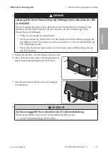
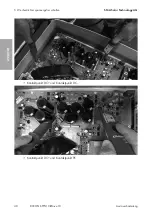
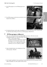
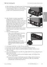
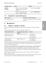
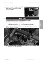
17. Die DC-Schutzabdeckung wieder befestigen. Dabei

die 4 Schrauben in der Reihenfolge 1 bis 4
anziehen (Innensechskant, SW3, Drehmoment: 3,5
Nm).

18. Den Wechselrichter wieder in Betrieb nehmen (siehe Kapitel 8, Seite 48).

8

Wechselrichter wieder in Betrieb nehmen

1. Erforderliche Prüfungen zur korrekten Wiederinbetriebnahme nach Baugruppentausch gemäß

aller vor Ort geltenden Gesetze, Normen und Richtlinien durchführen. Dabei Bedingungen für
den Komponententausch berücksichtigen (siehe Kapitel 2.2 "Wichtige Sicherheitshinweise",
Seite 31).

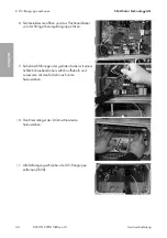
2. Sicherstellen, dass der Schutzleiter im Wechselrichter korrekt angeschlossen ist und die

Funktion des Schutzleiters gegeben ist.

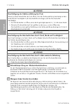
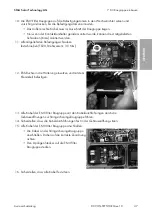
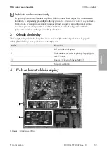
3. Den oberen Gehäusedeckel auf das Gehäuse setzen und alle Schrauben leicht anziehen.
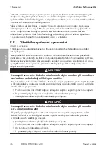
4. Die Schrauben des Gehäusedeckels in der

vorgegebenen Reihenfolge anziehen (SW4,
Drehmoment: 6 Nm ± 0,3 Nm).

2 3


4

56

789


AB

0

F

E

D

2 3


4

56

789


AB

0

F

E

D

2 3


4

56

789


AB

0

F

E

D

A

B

C

1

2

3

4

5

6

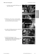
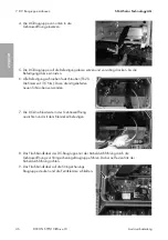
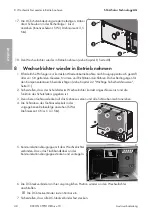
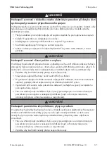
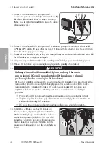
5. Kommunikationsbaugruppe mit dem Wechselrichter

verbinden. Dazu das Flachbandkabel an der
Kommunikationsbaugruppe stecken und verriegeln.

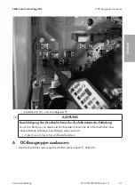
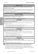
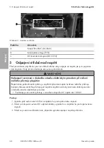
6. Die DC-Steckverbinder an ihrer ursprünglichen Position wieder an den Wechselrichter

anschließen.

☑ Die DC-Steckverbinder rasten hörbar ein.

7. Sicherstellen, dass alle DC-Steckverbinder fest stecken.

DEUTSCH

Содержание NR-STP-DC-CON-1012

Страница 1: ...DCCON STPTL10 RM xx 10 120589 00 01 Version 1 0 Spare part set DC assembly for Sunny Tripower 8000TL 10000TL 12000TL 15000TL 17000TL NR STP DC CON 1012 NR3 STP DCCON1012 NR STP DC CON NR3 STP DC CON...

Страница 2: ...k v m n 51 74 ESPA OL Instrucciones para la sustituci n 99 FRAN AIS Instructions de remplacement 123 ITALIANO Istruzioni per la sostituzione 147 NEDERLANDS Vervangingshandleiding 171 PORTUGU S Manual...

Страница 3: ...any indirect incidental or consequential damages under any circumstances The exclusion of implied warranties may not apply in all cases under some statutes and thus the above exclusion may not apply S...

Страница 4: ...1 5 Levels of Warning Messages 6 1 6 Typographical Elements in the Document 6 1 7 Designations in the Document 7 2 Safety 7 2 1 Intended Use 7 2 2 IMPORTANT SAFETY INSTRUCTIONS 7 3 Scope of Delivery...

Страница 5: ...e activities described in this document This ensures the quality requirements for proper replacement of assemblies The type of training and the media used may vary from country to country Knowledge of...

Страница 6: ...ry CAUTION Indicates a hazardous situation which if not avoided could result in minor or moderate injury NOTICE Indicates a situation which if not avoided can result in property damage 1 6 Typographic...

Страница 7: ...nd in most cases terminate the operating license SMA Solar Technology AG shall not be held liable for any damage caused by such changes Any use of the product other than that described in the Intended...

Страница 8: ...ts or cables DANGER Danger to life due to electric shock when live components or DC cables are touched When exposed to light the PV modules generate high DC voltage which is present in the DC cables T...

Страница 9: ...RNING Risk of injury due to toxic substances gases and dusts In rare cases damages to electronic components can result in the formation of toxic substances gases or dusts inside the inverter Touching...

Страница 10: ...arge Touching electronic components can cause damage to or destroy the inverter through electrostatic discharge Ground yourself before touching any component Grounding conductor test prior to recommis...

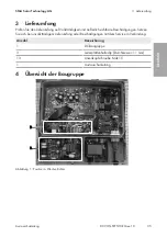
Страница 11: ...xx 10 11 Quantity Designation 3 Printed circuit board mounting clip diameter 11 mm 13 Pan head screw M4x15 1 Replacement Manual 4 Overview of the Assembly B A Figure 1 Position in the inverter C Figur...

Страница 12: ...dure 1 Disconnect the circuit breaker from all three line conductors and secure against reconnection 2 If an additional DC load break switch is available switch off the DC load break switch and secure...

Страница 13: ...N and L3 and N Insert the test probe into each round opening of the terminal 10 Use an appropriate measuring device to ensure that no voltage is present at the AC terminal block between L1 and PE L2...

Страница 14: ...ted gloves and use insulated tools when working on the DC connectors Ensure that the DC connectors are in perfect condition and that none of the DC conductors or DC plug contacts are exposed Carefully...

Страница 15: ...rter take 20 minutes to discharge Wait 20 minutes before opening the upper enclosure lid Unscrew all screws of the upper enclosure lid AF4 and remove the upper enclosure lid 19 Discharge the DC link i...

Страница 16: ...ng conductor 20 NOTICE Damage to the inverter due to electrostatic discharge Touching electronic components can cause damage to or destroy the inverter through electrostatic discharge Ground yourself...

Страница 17: ...llen key AF 3 and remove the DC protective cover 3 Disconnect the cable connections Remove all cables connected to the assembly of the EMC filtering device on the string fuse assembly Remove the 8 pol...

Страница 18: ...nector To do so loosen the clamping clip of the ESS pin connector using a flat blade screwdriver and pull out the ESS pin connector 6 Remove the marked connecting screws on the assembly of the EMC fil...

Страница 19: ...nal and remove the ribbon cable from the string fuse assembly 9 Pry out the cable glands of the removed cables sideways using a flat blade screwdriver and pull out downwards together with the cables 1...

Страница 20: ...Assembly 1 Check whether the PCB retaining clips 2 3 and 4 are still inserted If not insert the 3 PCB retaining clips from the scope of delivery Check whether both external PCB retaining clips 1 and 5...

Страница 21: ...rews supplied for this 7 Align the DC terminal block in the enclosure opening and attach using the clamping clip 8 Lead the DC assembly ribbon cable with the cable gland through the enclosure opening...

Страница 22: ...n the bracket and attach using the clamping clip 13 Lead all cables with the cable glands of the assembly of the EMC filtering device through the enclosure openings to the string fuse assembly 14 Ensu...

Страница 23: ...S page 7 2 Ensure that the grounding conductor in the inverter is correctly connected and functions properly 3 Mount the upper enclosure lid onto the enclosure and lightly fasten all screws 4 Tighten...

Страница 24: ...damage If the metal mounting tabs show brown discoloration or are damaged order a new ESS from SMA Solar Technology AG and have the ESS replaced If the metal mounting tabs show no brown discoloration...

Страница 25: ...d event message appear in the display The inverter has detected an error Eliminate the error see the inverter manual 17 Ensure that the inverter feed in correctly 9 Returning and Disposing of the Defe...

Страница 26: ...zuf llige Folgeverluste oder Sch den Der oben genannte Ausschluss von impliziten Gew hrleistungen kann nicht in allen F llen angewendet werden nderungen an Spezifikationen bleiben vorbehalten Es wurde...

Страница 27: ...m Dokument 28 1 5 Warnhinweisstufen 29 1 6 Auszeichnungen im Dokument 29 1 7 Benennungen im Dokument 30 2 Sicherheit 30 2 1 Bestimmungsgem e Verwendung 30 2 2 Wichtige Sicherheitshinweise 31 3 Lieferu...

Страница 28: ...er in diesem Dokument beschriebenen T tigkeiten Dadurch werden die Qualit tsanforderungen f r einen ordnungsgem en Austausch von Baugruppen sichergestellt Die Art der Schulung und die verwendeten Medi...

Страница 29: ...chtbeachtung zum Tod oder zu schweren Verletzungen f hren kann VORSICHT Kennzeichnet einen Warnhinweis dessen Nichtbeachtung zu leichten oder mittleren Verletzungen f hren kann ACHTUNG Kennzeichnet ei...

Страница 30: ...0 NR STP DC CON NR3 STP DC CON STP DC CON xx xx STP 15000TL 10 STP 17000TL 10 Setzen Sie SMA Produkte ausschlie lich nach den Angaben der beigef gten Dokumentationen und gem der vor Ort g ltigen Geset...

Страница 31: ...geschlossen 2 2 Wichtige Sicherheitshinweise Anleitung aufbewahren Dieses Kapitel beinhaltet Sicherheitshinweise die bei allen Arbeiten immer beachtet werden m ssen Das Produkt wurde gem international...

Страница 32: ...nen Bei allen Arbeiten geeignete pers nliche Schutzausr stung tragen GEFAHR Lebensgefahr durch Stromschlag beim Ber hren unter Spannung stehender Anlagenteile bei einem Erdschluss Bei einem Erdschluss...

Страница 33: ...und Atemschutz durchf hren WARNUNG Verletzungsgefahr durch giftige Substanzen Gase und St ube In seltenen Einzelf llen k nnen durch Besch digungen an elektronischen Bauteilen giftige Substanzen Gase...

Страница 34: ...brechung und nach Beenden der Arbeiten den Wechselrichter schlie en ACHTUNG Besch digung des Wechselrichters durch elektrostatische Entladung Durch das Ber hren von elektronischen Bauteilen k nnen Sie...

Страница 35: ...eit und u erlich sichtbare Besch digungen Setzen Sie sich bei unvollst ndigem Lieferumfang oder Besch digungen mit dem Service in Verbindung Anzahl Bezeichnung 1 DC Baugruppe 3 Leiterplattenhalteclip...

Страница 36: ...Messger ts durch berspannung Eine berspannung kann ein Messger t besch digen und zum Anliegen einer Spannung am Geh use des Messger ts f hren Das Ber hren des unter Spannung stehenden Geh uses des Me...

Страница 37: ...sches Signal ert nt und das Display eine Fehlermeldung anzeigt die das Abziehen des ESS verbietet warten bis es dunkel ist Erst bei Dunkelheit kann der ESS abgezogen werden Wenn kein akustisches Signa...

Страница 38: ...C Steckverbinder notieren um sie sp ter an derselben Position wieder anschlie en zu k nnen 14 GEFAHR Lebensgefahr durch Stromschlag beim Ber hren freigelegter DC Leiter oder DC Steckerkontakte bei bes...

Страница 39: ...am Kabel ziehen 1 2 16 Spannungsfreiheit an den DC Eing ngen des Wechselrichters feststellen 17 Kommunikationsbaugruppe vom Wechselrichter trennen Dazu das Flachbandkabel an der Kommunikationsbaugrup...

Страница 40: ...5 Wechselrichter spannungsfrei schalten SMA Solar Technology AG Austauschanleitung DCCON STPTL10 RM xx 10 40 Kontaktpunkt DC und Kontaktpunkt DC Kontaktpunkt DC und Kontaktpunkt PE DEUTSCH...

Страница 41: ...h digung des Wechselrichters durch elektrostatische Entladung Durch das Ber hren von elektronischen Bauteilen k nnen Sie den Wechselrichter ber elektrostatische Entladung besch digen oder zerst ren Er...

Страница 42: ...hskant Schl ssel SW 3 herausdrehen und die DC Schutzabdeckung abnehmen 3 Kabelverbindungen l sen Alle Verbindungskabel auf der Stringsicherungs Baugruppe zur EMV Filter Baugruppe l sen Den 8 poligen S...

Страница 43: ...hse ausbauen Dazu mit einem Schlitz Schraubendreher den Klemmkeil der ESS Buchse l sen und die ESS Buchse herausziehen 6 Die markierten Befestigungsschrauben auf der EMV Filter Baugruppe entfernen TX2...

Страница 44: ...Flachbandkabel von der Stringsicherungs Baugruppe l sen 9 Kabeldurchf hrungen der gel sten Kabel mit einem Schlitz Schraubendreher seitlich aufhebeln und zusammen mit den Kabeln nach unten herausziehe...

Страница 45: ...gruppe einbauen 1 Pr fen ob die Leiterplattenhalteclips 2 3 und 4 noch stecken Falls nicht die drei Leiterplattenhalteclips aus dem Lieferumfang aufstecken Pr fen ob die beiden u eren Leiterplattenhal...

Страница 46: ...tigungsschrauben festschrauben TX20 Drehmoment 3 5 Nm Dazu die mitgelieferten neuen Schrauben verwenden 7 Die DC Anschlussleiste in der Geh use ffnung ausrichten und mit dem Klemmkeil befestigen 8 Das...

Страница 47: ...mitgelieferten Befestigungsschrauben festschrauben TX20 Drehmoment 3 5 Nm 12 ESS Buchse in die Halterung einsetzen und mit dem Klemmkeil befestigen 13 Alle Kabel der EMV Filter Baugruppe mit den Kabe...

Страница 48: ...ge Sicherheitshinweise Seite 31 2 Sicherstellen dass der Schutzleiter im Wechselrichter korrekt angeschlossen ist und die Funktion des Schutzleiters gegeben ist 3 Den oberen Geh usedeckel auf das Geh...

Страница 49: ...zung pr fen Pr fen ob die Metallzungen im Inneren des ESS verf rbt oder besch digt sind Wenn die Metallzungen br unlich verf rbt oder besch digt sind neuen ESS bei SMA Solar Technology AG bestellen un...

Страница 50: ...en im Display Der Wechselrichter hat einen Fehler erkannt Fehler beheben siehe Anleitung des Wechselrichters 17 Sicherstellen dass der Wechselrichter fehlerfrei einspeist 9 Defekte Baugruppe zur cksen...

Страница 51: ...ep m i n hodn n sledn ztr ty nebo kody V e uvedenou v luku implicitn ch z ruk nelze aplikovat ve v ech p padech Vyhrazujeme si pr vo na zm ny specifikac Maxim ln usilujeme o to abychom tento dokument...

Страница 52: ...a n ch upozorn n 54 1 6 Typografick konvence v dokumentu 54 1 7 Ozna en v tomto dokumentu 55 2 Bezpe nost 55 2 1 Pou it v souladu s ur en m 55 2 2 D le it bezpe nostn upozorn n 56 3 Obsah dod vky 59 4...

Страница 53: ...psan ch v tomto dokumentu ast na kolen spole nosti SMA T m zajist te spln n kvalitativn ch po adavk pro dnou v m nu konstruk n ch skupin Druh kolen a pou it m dia se mohou odchylovat podle specifick c...

Страница 54: ...stra n upozorn n jeho nerespektov n m e v st k usmrcen nebo k t k mu poran n UPOZORN N Ozna uje v stra n upozorn n jeho nerespektov n m e v st lehk mu nebo st edn t k mu poran n OZN MEN Ozna uje v str...

Страница 55: ...TL 10 STP 12000TL 10 NR STP DC CON NR3 STP DC CON STP DC CON xx xx STP 15000TL 10 STP 17000TL 10 Produkty SMA pou vejte pouze podle daj uveden ch v p ilo en dokumentaci a podle z kon ustanoven p edpis...

Страница 56: ...j hroz navzdory pe liv mu zkonstruov n zbytkov rizika Aby se p ede lo poran n osob a vzniku materi ln ch kod a aby byl zaji t n trval provoz produktu pozorn si tuto kapitolu p e t te a v dy dbejte v e...

Страница 57: ...mi nebo vymr t n mi d ly Zajist te aby ke st da i nem ly p stup nepovolan osoby Nevytahujte odp na Electronic Solar Switch ESS na st da i FV gener tor odpojte od st da e extern m odpojovac m za zen m...

Страница 58: ...t da otev t p i mrazu odstra te p ed jeho otev en m p padnou n mrazu na t sn n t lesa nap tak e ji rozpust te tepl m vzduchem OZN MEN Po kozen st da e p skem prachem a vlhkost Vnik n m p sku prachu a...

Страница 59: ...sti za vady a zpravidla tak k z niku povolen k provozu Odpov dnost spole nosti SMA Solar Technology AG za kody zp soben v d sledku takov ch z sah je vylou ena 3 Obsah dod vky Zkontrolujte zda je dod v...

Страница 60: ...smrcen v d sledku z sahu elektrick m proudem p i zni en m ic ho p stroje p ep t m P ep t m e po kodit m ic p stroj a zap init p iveden nap t na t leso m ic ho p stroje Kontakt s t lesem m ic ho p stro...

Страница 61: ...da se oz v akustick sign l Pokud se oz v akustick sign l a na displeji se zobrazuje chybov hl en kter zakazuje odpojen odp na e ESS po kejte dokud nebude tma Odp na ESS lze odpojit a za tmy Pokud se n...

Страница 62: ...k m proudem p i kontaktu s obna en mi DC vodi i nebo kontakty DC konektoru v p pad po kozen ch nebo uvoln n ch DC konektor P i chybn m odji t n a odpojen DC konektor mohou DC konektory prasknout po ko...

Страница 63: ...e ploch kabel na komunika n m modulu 18 NEBEZPE Nebezpe usmrcen vlivem vysok ho nap t ve st da i Kondenz tory ve st da i pot ebuj k vybit 20 minut Po kejte 20 minut ne otev ete horn v ko krytu Vy roub...

Страница 64: ...5 Odpojen st da e od nap t SMA Solar Technology AG N vod k v m n DCCON STPTL10 RM xx 10 64 Kontaktn bod DC a kontaktn bod PE E TINA...

Страница 65: ...m v bojem Ne se dotknete kter koli sou stky uzemn te se 6 Demont DC konstruk n skupiny 1 Odpojte st da od nap t viz kapitola 5 strana 60 2 Kl em s vnit n m estihranem vel 3 vy roubujte v echny ty i r...

Страница 66: ...ze strany vypa te ploch m roubov kem Kabely s kabelov mi pr chodkami vyt hn te sm rem dol 5 Demontujte z suvku odp na e ESS Za t mto elem ploch m roubov kem uvoln te up nac kl n z suvky odp na e ESS...

Страница 67: ...h d m a vyndejte ji Tip K odji t n upev ovac ch d m pou ijte n str n kl vel 4 8 Otev ete svorku s feritov m j drem a od konstruk n skupiny stringov pojistky odpojte ploch kabel 9 Kabelov pr chodky uvo...

Страница 68: ...ign lov ho kabelu na DC konstruk n skupin a kabel si uschovejte pro op tovn pou it na nov DC konstruk n skupin 7 Mont DC konstruk n skupiny 1 Zkontrolujte zda jsou je t zapojeny p chytky desky plo n c...

Страница 69: ...zespodu vsa te DC konstruk n skupinu 5 DC konstruk n skupinu nasa te na upev ovac d my a opatrn na ni zatla te tak aby se upev ovac d my zajistily 6 Za roubujte v echny upev ovac rouby TX20 to iv mome...

Страница 70: ...zet ve v ezu konstruk n skupiny ty i dodan rouby krou ek lze namontovat jen tehdy pokud byl dr k kontaktn ch d m namontov n rovn 11 Za roubujte v echny dodan upev ovac rouby TX20 to iv moment 3 5 Nm...

Страница 71: ...rana 71 8 Op tovn uveden st da e do provozu 1 Prove te kontroly pot ebn pro dn op tovn uveden do provozu po v m n konstruk n skupiny v souladu se v emi z kony normami a sm rnicemi platn mi na m st ins...

Страница 72: ...kl e s vnit n m estihranem vel 3 v po ad 1 a 6 to iv moment 2 0 Nm 0 3 Nm Dodr en m po ad zamez te tomu aby bylo v ko krytu p i roubov no na ikmo a aby byl kryt net sn Tip Pokud ze spodn ho v ka krytu...

Страница 73: ...stav distribu n s t Po kejte dokud nebude vstupn DC nap t dostate n vysok nebo dokud nebudou spln ny podm nky pro p ipojen k s ti St da pak auto maticky p ejde do provozu Sv t erven LED dioda a na dis...

Страница 74: ...Solar Technology AG SMA Solar Technology AG SMA Solar Technology AG SMA Solar Technology AG SMA Solar Technology AG SMA Solar Technology AG Sonnenallee 1 34266 Niestetal 49 561 9522 0 49 561 9522 100...

Страница 75: ...SMA Solar Technology AG DCCON STPTL10 RM xx 10 75 1 76 1 1 76 1 2 76 1 3 76 1 4 76 1 5 77 1 6 77 1 7 78 2 78 2 1 78 2 2 79 3 83 4 83 5 84 6 DC 89 7 DC 93 8 96 9 98...

Страница 76: ...1 SMA Solar Technology AG DCCON STPTL10 RM xx 10 76 1 1 1 NR STP DC CON 1012 NR3 STP DCCON1012 NR STP DC CON NR3 STP DC CON 1 2 SMA SMA SMA SMA Solar Technology AG SMA SMA 1 3 1 4...

Страница 77: ...1 SMA Solar Technology AG DCCON STPTL10 RM xx 10 77 1 5 1 6 X703 1 X703 6 10...

Страница 78: ...7 DC DC DC CON 2 2 1 DC DC CON SMA SMA NR STP DC CON 1012 NR3 STP DCCON1012 STP DC CON 1012 xx xx STP 8000TL 10 STP 10000TL 10 STP 12000TL 10 NR STP DC CON NR3 STP DC CON STP DC CON xx xx STP 15000TL...

Страница 79: ...2 SMA Solar Technology AG DCCON STPTL10 RM xx 10 79 SMA Solar Technology AG SMA Solar Technology AG 2 2...

Страница 80: ...2 SMA Solar Technology AG DCCON STPTL10 RM xx 10 80 DC DC DC DC 5...

Страница 81: ...2 SMA Solar Technology AG DCCON STPTL10 RM xx 10 81 Electronic Solar Switch ESS DC AC DC 1000 V...

Страница 82: ...2 SMA Solar Technology AG DCCON STPTL10 RM xx 10 82 5 C v v SMA SMA...

Страница 83: ...3 SMA Solar Technology AG DCCON STPTL10 RM xx 10 83 SMA Solar Technology AG 3 1 DC 3 11 mm 13 M4x15 1 4 B A 1...

Страница 84: ...5 SMA Solar Technology AG DCCON STPTL10 RM xx 10 84 C 2 A HM DC EMV B PVS C DC DC CON 5 DC 1000 V 1 3 2 DC 3...

Страница 85: ...5 SMA Solar Technology AG DCCON STPTL10 RM xx 10 85 4 ESS ESS ESS ESS ESS 5 LED 6 6 3 7 8 DC DC DC...

Страница 86: ...5 SMA Solar Technology AG DCCON STPTL10 RM xx 10 86 9 AC L1 N L2 N L3 N 10 AC L1 PE L2 PE L3 PE 11 PE AC 12 DC 13 DC 14 DC DC DC DC DC DC DC DC DC DC DC DC DC DC DC...

Страница 87: ...5 SMA Solar Technology AG DCCON STPTL10 RM xx 10 87 15 DC 3 5 mm DC DC 1 2 16 DC 17 18 20 20 4 19 2...

Страница 88: ...5 SMA Solar Technology AG DCCON STPTL10 RM xx 10 88 DC DC DC PE...

Страница 89: ...6 DC SMA Solar Technology AG DCCON STPTL10 RM xx 10 89 DC PE 20 v v 6 DC 1 5 84...

Страница 90: ...6 DC SMA Solar Technology AG DCCON STPTL10 RM xx 10 90 2 4 DC 3 DC 3 8 4...

Страница 91: ...6 DC SMA Solar Technology AG DCCON STPTL10 RM xx 10 91 5 ESS ESS ESS 6 TX20 7 4...

Страница 92: ...6 DC SMA Solar Technology AG DCCON STPTL10 RM xx 10 92 8 9 10 DC 11 DC TX20...

Страница 93: ...7 DC SMA Solar Technology AG DCCON STPTL10 RM xx 10 93 12 DC 13 DC DC 14 8 DC DC 7 DC 1 2 3 4 1 5 DC 1 2 3 4 5 2 DC 3 8 DC...

Страница 94: ...7 DC SMA Solar Technology AG DCCON STPTL10 RM xx 10 94 4 DC 5 DC 6 TX20 3 5 Nm 7 DC 8 DC 9...

Страница 95: ...7 DC SMA Solar Technology AG DCCON STPTL10 RM xx 10 95 10 4 11 TX20 3 5 Nm 12 ESS 13 14 15 8 16...

Страница 96: ...gy AG DCCON STPTL10 RM xx 10 96 17 DC 4 1 4 3 3 5 Nm 18 8 96 8 1 2 2 79 2 3 4 4 6 Nm 0 3 Nm 2 3 1 4 5 6 7 8 9 C A B 0 F E D 2 3 1 4 5 6 7 8 9 C A B 0 F E D 2 3 1 4 5 6 7 8 9 C A B 0 F E D A B C 1 2 3...

Страница 97: ...8 SMA Solar Technology AG DCCON STPTL10 RM xx 10 97 8 DC DC 9 10 6 3 1 6 2 0 Nm 0 3 Nm 5 11 ESS ESS ESS SMA Solar Technology AG ESS 12 3 13 firmware 14 ESS ESS 15 3 LED LED firmware NetID...

Страница 98: ...9 SMA Solar Technology AG DCCON STPTL10 RM xx 10 98 16 LED LED LED DC DC LED 17 9 1 SMA Solar Technology AG 2...

Страница 99: ...ultante bajo ninguna circunstancia La exclusi n de garant as impl citas puede no ser aplicable en todos los casos seg n algunos estatutos y por tanto la exclusi n mencionada anteriormente puede no ser...

Страница 100: ...iveles de advertencia 102 1 6 Marcas de texto en el documento 102 1 7 Denominaci n en el documento 103 2 Seguridad 103 2 1 Uso previsto 103 2 2 Indicaciones importantes para la seguridad 104 3 Conteni...

Страница 101: ...n el presente documento As se garantizan los requisitos de calidad necesarios para sustituir correctamente los subgrupos El tipo de formaci n y los medios utilizados pueden diferir de un pa s a otro C...

Страница 102: ...o ser observada puede causar la muerte o lesiones f sicas graves ATENCI N Representa una advertencia que de no ser observada puede causar lesiones f sicas leves o de gravedad media PRECAUCI N Represen...

Страница 103: ...adjunta y observe las leyes reglamentos reglas y normas vigentes Cualquier otro uso puede causarle lesiones al usuario o da os materiales Para realizar cualquier intervenci n en los productos de SMA c...

Страница 104: ...lo y cumpla siempre las indicaciones de seguridad PELIGRO Peligro de muerte por descarga el ctrica por contacto con componentes conductores de tensi n o cables del inversor En los componentes conducto...

Страница 105: ...r fuego y explosi n En infrecuentes casos aislados puede producirse en caso de error una mezcla de gas inflamable en el interior del inversor En este estado puede producirse un incendio en el interior...

Страница 106: ...po de medici n por una sobretensi n Una sobretensi n puede da ar un equipo de medici n y provocar que exista tensi n en la carcasa del equipo de medici n Tocar la carcasa del equipo de medici n bajo t...

Страница 107: ...onentes de SMA o subgrupos de potencia que no se puedan sustituir de forma intuitiva aseg rese de que el conductor de protecci n del inversor est conectado correctamente El conductor de protecci n deb...

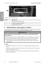
Страница 108: ...el inversor C Imagen 2 Posici n en el inversor Posici n Denominaci n A Subgrupo del filtro CEM DC EMV B Subgrupo del fusible de string PVS C Subgrupo de CC DC CON 5 Desconexi n del inversor de la tens...

Страница 109: ...r seccionador de potencia de CC externo descon ctelo y aseg relo contra cualquier reconexi n 3 Si se utiliza el rel multifunci n desconecte en caso necesario la tensi n de alimentaci n del equipo cons...

Страница 110: ...y N Para ello introduzca la punta de comprobaci n en el agujero redondo de cada borne 10 Compruebe sucesivamente con un equipo de medici n adecuado que no haya tensi n en la caja de bornes de CA entr...

Страница 111: ...el ctrica Al realizar trabajos en los contactores de enchufe CC utilizar guantes y herramientas con el debido aislamiento Asegurarse de que los conectores de enchufe CC se encuentren en estado impeca...

Страница 112: ...inutos en descargarse Espere 20 minutos antes de abrir la tapa superior de la carcasa Desenrosque todos los tornillos de la tapa de la carcasa superior ancho 4 y retire la tapa superior 19 Descargue e...

Страница 113: ...e contacto PE 20 PRECAUCI N Da os en el inversor por descarga electrost tica Si toca componentes electr nicos puede da ar o destruir el inversor debido a una descarga electrost tica P ngase a tierra a...

Страница 114: ...tecci n de CC utilizando una llave Allen ancho 3 y retire la cubierta 3 Afloje las conexiones de cable Suelte todos los cables de conexi n del subgrupo del fusible de string del subgrupo del filtro CE...

Страница 115: ...nte la hembrilla del ESS Para ello suelte con un destornillador plano la cu a de sujeci n de la hembrilla del ESS y extraiga la hembrilla del ESS 6 Retire los tornillos de fijaci n marcados del subgru...

Страница 116: ...rita y suelte el cable plano del subgrupo del fusible de string 9 Levante lateralmente las aberturas en la carcasa de los cables soltados con un destornillador plano y tire de ellas hacia abajo junto...

Страница 117: ...insertan las pinzas de agarre de las placas de circuito 2 3 y 4 Si no lo hacen inserte las pinzas de agarre de las placas de circuito del contenido de la entrega Compruebe si las dos pinzas de agarre...

Страница 118: ...los tornillos de fijaci n TX20 par de apriete 3 5 Nm Para esto utilice los nuevos tornillos suministrados 7 Oriente la regleta de terminales de CC a la abertura en la carcasa y f jela con la cu a de...

Страница 119: ...os tornillos de fijaci n suministrados TX20 par de apriete 3 5 Nm 12 Inserte la hembrilla del ESS en el soporte y f jela con la cu a de sujeci n 13 Lleve todos los cables del subgrupo del filtro CEM c...

Страница 120: ...na 104 2 Aseg rese de que el conductor de protecci n del inversor est correctamente conectado y de que el conductor de protecci n funcione correctamente 3 Coloque la tapa de la carcasa superior en la...

Страница 121: ...una coloraci n pardusca o est n da adas Si las leng etas met licas presentan una coloraci n pardusca o est n da adas contacte con SMA Solar Technology AG para solicitar un nuevo ESS y sustituya el ES...

Страница 122: ...y en la pantalla apare cen un mensaje de error y un avi so de evento El inversor ha detectado un fallo Elimine el error consulte las instruc ciones del inversor 17 Aseg rese de que el inversor inyecte...

Страница 123: ...pectifs ne sauraient et ce sous aucune circonstance tre tenus responsables en cas de pertes ou de dommages directs indirects ou accidentels L exclusion susmentionn e des garanties implicites peut ne p...

Страница 124: ...Niveaux de mise en garde 126 1 6 Formats utilis s dans le document 126 1 7 D signations utilis es dans le document 127 2 S curit 127 2 1 Utilisation conforme 127 2 2 Consignes de s curit importantes...

Страница 125: ...nt Cela permet de garantir que les exigences de qualit pour un remplacement en bonne et due forme des ensembles sont satisfaites Le type de formation et les m dias utilis s peuvent varier d un pays l...

Страница 126: ...t le non respect peut entra ner des blessures corporelles graves voire la mort ATTENTION Indique une mise en garde dont le non respect peut entra ner des blessures corporelles l g res ou de moyenne gr...

Страница 127: ...P DC CON STP DC CON xx xx STP 15000TL 10 STP 17000TL 10 Utilisez des produits SMA exclusivement en conformit avec la documentation fournie ainsi qu avec les lois dispositions prescriptions normes et d...

Страница 128: ...lis avec le plus grand soin comme pour tout appareil lectrique lectronique il existe des risques r siduels Lisez ce chapitre attentivement et respectez en permanence toutes les consignes de s curit po...

Страница 129: ...vous que les personnes non autoris es ne peuvent pas acc der l onduleur Ne retirez pas l Electronic Solar Switch ESS au niveau de l onduleur D connectez le g n rateur photovolta que de l onduleur via...

Страница 130: ...le le joint pourra tre endommag De l humidit peut donc p n trer dans l onduleur et l endommager N ouvrez l onduleur que si la temp rature ambiante n est pas inf rieure 5 C Si vous devez ouvrir l ondul...

Страница 131: ...paration de l appareil rel ve de la responsabilit du personnel qualifi charg tout en tenant compte et en appliquant les normes suppl mentaires correspondant une norme sup rieure Toute intervention no...

Страница 132: ...igure 1 Position dans l onduleur C Figure 2 Position dans l onduleur Position D signation A Module de filtre CEM DC EMV B Module de fusible string PVS C Ensemble DC DC CON 5 Mise hors tension de l ond...

Страница 133: ...errupteur sectionneur DC et prot gez le contre la remise en marche 3 Si vous utilisez le relais multifonction d sactivez le cas ch ant la tension d alimentation de la charge 4 DANGER Danger de mort pa...

Страница 134: ...t N et L3 et N Pour ce faire ins rez la pointe de contr le dans l ouverture ronde de la borne 10 l aide d un appareil de mesure appropri v rifiez que la plaque bornes AC est bien hors tension entre L1...

Страница 135: ...ectu s sur des connecteurs DC portez toujours des gants de protection et utilisez des outils isol s Assurez vous que les connecteurs DC sont en parfait tat et qu aucun conducteur DC ou contact de conn...

Страница 136: ...tendez 20 minutes avant d ouvrir le couvercle sup rieur du bo tier D vissez toutes les vis du couvercle sup rieur du bo tier SW4 et retirez le couvercle sup rieur du bo tier 19 D chargez le circuit in...

Страница 137: ...tact PE 20 PRUDENCE Endommagement de l onduleur par une d charge lectrostatique En touchant les composants lectroniques vous pouvez endommager voire d truire l onduleur par d charge lectrostatique Rel...

Страница 138: ...r vis six pans creux surplat de 3 et retirez le capot 3 Desserrez les raccords des c bles Desserrez tous les c bles de raccordement de l ensemble de fusibles string vers l ensemble de filtre CEM D tac...

Страница 139: ...ontez l embase de l ESS Pour ce faire desserrez la cale de serrage de l embase de l ESS l aide d un tournevis fente et retirez l embase 6 Retirez les vis de fixation marqu es sur l ensemble de filtre...

Страница 140: ...our noyau de ferrite et d branchez le c ble plat de l ensemble de fusibles string 9 Soulevez lat ralement les ouvertures de bo tier des c bles d branch s l aide d un tournevis fente et tirez tous les...

Страница 141: ...rifiez si les clips de fixation 2 3 et 4 sont toujours bien enclench s Si ce n est pas le cas placez les trois clips de fixation fournis dans le contenu de livraison V rifiez si les deux clips de fix...

Страница 142: ...aire utilisez les vis neuves fournies 7 Positionnez le bornier DC dans l ouverture de bo tier et fixez le l aide de la cale de serrage 8 Introduisez le c ble plat de l ensemble DC dans l ouverture de...

Страница 143: ...m 12 Introduisez l embase de l ESS dans le support et fixez la l aide de la cale de serrage 13 Introduisez tous les c bles de l ensemble de filtre CEM dans les ouvertures de bo tier de l ensemble de f...

Страница 144: ...omposants voir chapitre 2 2 Consignes de s curit importantes page 128 2 Assurez vous que le conducteur de protection dans l onduleur est correctement raccord et que son bon fonctionnement est garanti...

Страница 145: ...lez si les languettes m talliques l int rieur de l ESS sont d color es ou endommag es Commandez un ESS neuf chez SMA Solar Technology AG et remplacez l ESS si les languettes m talliques pr sentent un...

Страница 146: ...onduleur a d tect un d faut Corrigez le d faut voir instructions de l onduleur 17 Assurez vous que l onduleur injecte sans erreur dans le r seau 9 Renvoyer ou liminer le module de construction d fectu...

Страница 147: ...seguenti o danni diretti o indiretti La suddetta esclusione di garanzie di legge implicite non si applica in altri casi Con riserva di modifiche delle specifiche stato fatto il possibile per redigere...

Страница 148: ...velli delle avvertenze di sicurezza 150 1 6 Convenzioni tipografiche nel documento 150 1 7 Denominazioni nel documento 151 2 Sicurezza 151 2 1 Utilizzo conforme 151 2 2 Avvertenze di sicurezza importa...

Страница 149: ...e attivit descritte nel presente documento In questo modo vengono garantiti i requisiti di qualit per la corretta sostituzione dei gruppi costruttivi Il tipo di formazione e i media utilizzati possono...

Страница 150: ...morte o lesioni gravi ATTENZIONE Identifica un avvertenza di sicurezza la cui inosservanza pu provocare lesioni leggere o medie AVVISO Identifica un avvertenza di sicurezza la cui inosservanza pu prov...

Страница 151: ...dei diritti di garanzia e di regola come anche la revoca dell autorizzazione di funzionamento esclusa ogni responsabilit di SMA Solar Technology AG per danni derivanti da tali interventi Non consenti...

Страница 152: ...presenti tensioni elevate Il contatto con componenti sotto tensione o cavi dell inverter pu determinare la morte o lesioni mortali per folgorazione Prima di qualsiasi intervento togliere tensione all...

Страница 153: ...tarsi che nessuna persona non autorizzata possa accedere all inverter Non staccare l Electronic Solar Switch ESS dall inverter Separare il generatore FV dall inverter mediante un dispositivo di sezion...

Страница 154: ...i gelo se si apre l inverter possibile danneggiare la guarnizione del coperchio Ci pu favorire la penetrazione di umidit nell inverter e danneggiarlo Aprire l inverter solo quando la temperatura ambie...

Страница 155: ...ializzato che esegue l intervento responsabile della riparazione dell apparecchio nonch del rispetto e dell applicazione di ulteriori norme che si rifanno a uno standard di livello superiore Eventuali...

Страница 156: ...nell inverter C Figura 2 Posizione nell inverter Posizione Denominazione A Gruppo filtro CEM DC EMV B Gruppo fusibile di stringa PVS C Gruppo CC CC CON 5 Disinserzione dell inverter Prima di eseguire...

Страница 157: ...e presente un sezionatore di carico CC esterno disattivarlo e assicurarlo contro la riattivazione 3 In caso di impiego di un rel multifunzione disinserire la tensione di alimentazione dell utilizzator...

Страница 158: ...3 ed N con un apposito apparecchio di misurazione A tale scopo inserire il sensore nell apertura rotonda dei morsetti 10 Verificare in sequenza l assenza di tensione sulla morsettiera CA fra L1 ed PE...

Страница 159: ...nei terminali CC indossare guanti con isolamento e utilizzare un attrezzo isolato Assicurarsi che i terminali CC siano in stato corretto e che non siano presenti conduttori CC o terminali CC scoperti...

Страница 160: ...ti per scaricarsi Attendere 20 minuti prima di aprire il coperchio superiore dell involucro Svitare tutte le viti del coperchio dell involucro superiore cacciavite da 4 e rimuoverlo 19 Scaricare il ci...

Страница 161: ...atto PE 20 AVVISO Danneggiamento dell inverter per scarica elettrostatica Il contatto con componenti elettronici pu provocare guasti o danni irrimediabili all inverter per scarica elettrostatica Scari...

Страница 162: ...o protettivo CC con una brugola da 3 e rimuoverlo 3 Staccare tutti i collegamenti tramite cavo Staccare tutti i collegamenti tramite cavo sul gruppo fusibile di stringa al gruppo filtro CEM Staccare i...

Страница 163: ...presa ESS A tale scopo allentare la linguetta di serraggio della presa ESS con un cacciavite a taglio ed estrarre la presa ESS 6 Rimuovere le viti di fissaggio contrassegnate sul gruppo filtro CEM TX2...

Страница 164: ...ntro del morsetto in ferrite e rimuovere il cavo piatto dal gruppo fusibile di stringa 9 Sollevare lateralmente i passacavi dei cavi staccati con un cacciavite a taglio ed estrarli verso il basso insi...

Страница 165: ...gruppo CC 1 Controllare se le clip del circuito stampato 2 3 e 4 sono ancora inserite In caso contrario applicare le tre clip del circuito stampato in dotazione Controllare se le due clip del circuito...

Страница 166: ...Utilizzare per il montaggio solo le viti in dotazione 7 Allineare la morsettiera CC nell apertura dell involucro e fissarla con la linguetta 8 Inserire il cavo piatto del gruppo CC con il passacavo at...

Страница 167: ...3 5 Nm 12 Inserire la presa ESS nel supporto e fissarla con la linguetta 13 Portare tutti i cavi del gruppo filtro CEM con i passacavi al gruppo fusibile di stringa attraverso le aperture dell involuc...

Страница 168: ...di sicurezza importanti pag 151 2 Accertarsi che il conduttore di protezione nell inverter sia collegato correttamente e che funzioni 3 Posizionare il coperchio dell involucro superiore sull involucr...

Страница 169: ...che all interno di ESS hanno cambiato colore o sono danneggiate Se le linguette hanno assunto una colorazione brunastra o sono danneggiate ordinare un nuovo ESS presso SMA Solar Technology AG e sostit...

Страница 170: ...un messaggio di er rore e un messag gio di evento L inverter ha rilevato un errore Eliminare l errore vedere le istruzio ni dell inverter 17 Accertarsi che l inverter immetta senza anomalie 9 Spedizi...

Страница 171: ...e bovengenoemde uitsluiting van impliciete garanties kan niet in alle gevallen worden toegepast Wijzigingen van specificaties blijven voorbehouden Dit document is met veel inspanning en uiterst zorgvu...

Страница 172: ...ocument 173 1 5 Niveaus veiligheidswaarschuwing 174 1 6 Markeringen in document 174 1 7 Benamingen in het document 175 2 Veiligheid 175 2 1 Reglementair gebruik 175 2 2 Belangrijke veiligheidsaanwijzi...

Страница 173: ...ment beschreven werkzaamheden Daardoor worden de kwaliteitseisen voor een correcte vervanging van modules gewaarborgd De inhoud van de scholing en de gebruikte media kunnen per land verschillen Veilig...

Страница 174: ...arvan het niet in acht nemen tot de dood of ernstig lichamelijk letsel kan leiden VOORZICHTIG Markeert een veiligheidsaanwijzing waarvan het niet in acht nemen tot licht of middelzwaar lichamelijk let...

Страница 175: ...e toepassingen kunnen tot persoonlijk letsel of materi le schade leiden Wijzigingen van SMA producten bijvoorbeeld veranderingen of montage van onderdelen zijn alleen toegestaan met uitdrukkelijke sch...

Страница 176: ...en en een lange levensduur van het product te garanderen GEVAAR Levensgevaar door elektrische schokken bij het aanraken van spanning geleidende onderdelen of kabels van de omvormer Op de spanningvoere...

Страница 177: ...of explosie In uitzonderlijke gevallen kan in geval van storing intern in de omvormer een ontvlambaar gasmengsel ontstaan Door schakelhandelingen kan in deze toestand intern in de omvormer een brand o...

Страница 178: ...estel bij overspanning Een overspanning kan een meettoestel beschadigen en elektrische spanning op de behuizing van het meettoestel veroorzaken Het aanraken van een onder spanning staande behuizing va...

Страница 179: ...jf stellen van SMA omvormers na de inbouw van niet intu tief te vervangen SMA componenten of vermogensmodules waarborgen dat de aardleiding in de omvormer correct is aangesloten De functie van de aard...

Страница 180: ...vangingshandleiding DCCON STPTL10 RM xx 10 180 4 Overzicht module B A Afbeelding 1 Positie in de omvormer C Afbeelding 2 Positie in de omvormer Positie Aanduiding A EMC filtermodule DC EMV B Module st...

Страница 181: ...e leidingbeveiligingsschakelaar van alle 3 de fasedraden uit en beveilig hem tegen opnieuw inschakelen 2 Als er een externe DC lastscheider aanwezig is schakel de DC lastscheider dan uit en beveilig h...

Страница 182: ...sen L1 en N L2 en N en L3 en N Steek hiervoor de meetstaaf telkens in de ronde opening van de desbetreffende aansluitklem 10 Verzeker u er achtereenvolgens met een daartoe geschikt meettoestel van dat...

Страница 183: ...heden aan de DC connectoren ge soleerde handschoenen en gebruik ge soleerd gereedschap Waarborg dat de DC connectoren in optimale conditie zijn en geen DC aders of DC connectorcontacten bloot liggen O...

Страница 184: ...bben 20 minuten nodig om te ontladen Wacht 20 minuten voordat u de bovenste behuizingsdeksel opent Draai alle schroeven van de bovenste behuizingsdeksel los SW4 en verwijder de deksel 19 Het tussencir...

Страница 185: ...Beschadiging van de omvormer door elektrostatische ontlading Door het aanraken van elektronische onderdelen kan de omvormer via elektrostatische ontlading onherstelbaar worden beschadigd Zorg dat u ge...

Страница 186: ...met een inbussleutel SW 3 los en verwijder de DC beschermkap 3 Kabelverbindingen losmaken Alle verbindingskabels op de stringzekeringmodule naar de EMC filtermodule losmaken De 8 polige stekker op de...

Страница 187: ...n 5 ESS bus demonteren Daarvoor met een platte schroevendraaier de klemwig van de ESS bus losmaken en de ESS bus uittrekken 6 De gemarkeerde bevestigingsschroeven op de EMC filtermodule verwijderen TX...

Страница 188: ...e bandkabel van de stringzekeringmodule losmaken 9 Kabeldoorvoeren van de losgemaakte kabel met een platte schroevendraaier aan de zijkant uittillen en samen met de kabels naar onderen toe uittrekken...

Страница 189: ...uwen 1 Controleer of de printplaatclips 2 3 en 4 nog vastzitten Indien dit niet het geval is de drie meegeleverde printplaatclips plaatsen Controleer of de beide buitenste printplaatclips 1 en 5 van d...

Страница 190: ...vestigingsschroeven vastschroeven TX20 koppel 3 5 Nm Gebruik daarvoor de meegeleverde nieuwe schroeven 7 De DC aansluitstrook in de opening in de behuizing uitrichten en met de klemwig bevestigen 8 De...

Страница 191: ...emonteerd 11 Alle meegeleverde bevestigingsschroeven vastschroeven TX20 koppel 3 5 Nm 12 ESS bus in de houder plaatsen en met de klemwig bevestigen 13 Alle kabels van de EMC filtermodule met de kabeld...

Страница 192: ...2 2 Belangrijke veiligheidsaanwijzingen pagina 176 2 Verzeker u ervan dat de aardleiding in de omvormer correct is aangesloten en de aardleiding correct werkt 3 Plaats de bovenste behuizingsdeksel op...

Страница 193: ...ge Controleer of de metalen lipjes binnen in de ESS verkleurd of beschadigd zijn Als de metalen lipjes bruin gekleurd of beschadigd zijn bestel dan een nieuwe ESS bij SMA Solar Technology AG en vervan...

Страница 194: ...op de display De omvormer heeft een fout her kend Los het probleem op zie handlei ding van de omvormer 17 Controleer of de omvormer foutloos voedt 9 Defecte module terugsturen of afvoeren U vindt in...

Страница 195: ...ectos ou indirectos A exclus o supracitada das garantias impl citas n o pode ser aplicada a todos os casos Reserva se o direito a altera es s especifica es Foram envidados todos os esfor os para redig...

Страница 196: ...ocumento 197 1 5 N veis de aviso 198 1 6 Sinaliza es no documento 198 1 7 Designa es no documento 199 2 Seguran a 199 2 1 Utiliza o prevista 199 2 2 Avisos de seguran a importantes 200 3 Material forn...

Страница 197: ...ra poder realizar as tarefas descritas neste documento Esta forma o garante os padr es de qualidade para uma substitui o correta dos m dulos O tipo da forma o e os meios utilizados podem divergir cons...

Страница 198: ...ssinala um aviso que se n o observado poder causar les es leves ou moderadas PRECAU O Assinala um aviso que se n o observado poder causar danos materiais 1 6 Sinaliza es no documento Sinaliza o Aplica...

Страница 199: ...relativos garantia bem como em regra a anula o da licen a de opera o A SMA Solar Technology AG n o assume qualquer responsabilidade por danos resultantes de tais interven es Qualquer outra utiliza o...

Страница 200: ...s elevadas O contacto com pe as e cabos condutores de tens o do inversor causa de morte ou ferimentos graves devido a choque el ctrico Seccionar completamente o inversor colocando o sem tens o e prote...

Страница 201: ...por pe as quentes ou projec o de fragmentos Garantir que pessoas n o autorizadas n o podem aceder ao inversor N o retirar o Electronic Solar Switch ESS do inversor Desconectar o gerador fotovoltaico...

Страница 202: ...el que a veda o da caixa se danifique Por conseguinte pode haver infiltra o de humidade no inversor e danificar o inversor Abrir o inversor apenas se a temperatura ambiente n o for inferior a 5 C Se o...

Страница 203: ...no aparelho e a observa o e aplica o de outras regras respeitantes a uma norma superior s o da responsabilidade do t cnico especializado em quest o Interven es n o autorizadas t m como consequ ncia a...

Страница 204: ...C Figura 2 Posi o no inversor Posi o Designa o A M dulo do filtro CEM DC EMV B M dulo do fus vel de string fus vel de string eletr nico C M dulo CC DC CON 5 Colocar o inversor sem tens o Antes de qua...

Страница 205: ...rno deslig lo e proteg lo contra uma reativa o 3 Se o rel multifun es for utilizado desligar a tens o de alimenta o do equipamento consumidor caso necess rio 4 PERIGO Perigo de morte devido a choque e...

Страница 206: ...e L3 e N Para isso enfiar a ponta de prova sempre na abertura redonda do terminal de liga o 10 Com um aparelho de medi o adequado determinar a aus ncia de tens o na r gua de terminais CA sucessivament...

Страница 207: ...de trabalhos nos conectores de ficha CC usar luvas e ferramentas isoladas Assegurar que os conectores de ficha CC se encontram num estado irrepreens vel e que n o existem condutores CC ou contactos de...

Страница 208: ...scarregarem Aguardar 20 minutos antes de abrir a tampa superior da caixa Desapertar todos os parafusos da tampa superior da caixa largura da chave 4 e retirar a tampa 19 Descarregar o circuito interme...

Страница 209: ...acto PE 20 PRECAU O Danos no inversor devido a descarga eletrost tica Ao tocar em componentes eletr nicos pode danificar ou destruir o inversor devido a descarga eletrost tica Efetue a liga o terra an...

Страница 210: ...tec o CC com uma chave Allen tamanho 3 e retirar a cobertura de protec o CC 3 Soltar as uni es de cabo Soltar todas as uni es de cabo no m dulo do fus vel de string para o m dulo do filtro CEM Desliga...

Страница 211: ...ntar a tomada ESS Para o efeito soltar a cunha de aperto da tomada ESS com uma chave de fendas Torx e extrair a tomada ESS 6 Remover os parafusos de fixa o marcados no m dulo do filtro CEM TX20 7 Solt...

Страница 212: ...rrite e soltar o cabo plano do m dulo do fus vel de string 9 Com uma chave de fendas levantar lateralmente as passagens para cabos dos cabos soltos e extrair juntamente com os cabos puxando para baixo...

Страница 213: ...vo m dulo CC 7 Montar o m dulo CC 1 Verificar se os clipes de reten o da placa de circuito 2 3 e 4 ainda est o inseridos Caso contr rio prender os tr s clipes de reten o da placa de circuito inclu dos...

Страница 214: ...dulo CC sobre as c pulas de fixa o e empurrar com cuidado at as c pulas de fixa o engatarem 6 Aparafusar todos os parafusos de fixa o TX20 bin rio 3 5 Nm Para isso utilizar os parafusos novos forneci...

Страница 215: ...dulo S quando o suporte da c pula de contacto tiver sido montado a direito que os 4 parafusos fornecidos c rculo podem ser montados 11 Aparafusar todos os parafusos de fixa o fornecidos TX20 bin rio 3...

Страница 216: ...as verifica es necess rias para a correcta recoloca o em servi o no seguimento da substitui o dos m dulos em conformidade com todas as leis normas e directivas vigentes no local Nestas verifica es te...

Страница 217: ...10 Com uma chave Allen tamanho 3 apertar bem todos os 6 parafusos na sequ ncia 1 a 6 bin rio 2 0 Nm 0 3 Nm Ao cumprir esta sequ ncia evitar que a tampa da caixa seja mal apertada e que a caixa n o ve...

Страница 218: ...uito reduzida ou o inversor est a monitorizar a rede el trica p blica Aguardar at a tens o de entra da CC ser suficiente e as condi es de liga o rede estiverem preen chidas De seguida o inversor entra...

Страница 219: ...luderea mai sus men ionat a garan iilor implicite nu poate fi aplicat n toate cazurile Ne rezerv m dreptul asupra modific rilor specifica iilor Au fost ntreprinse toate eforturile pentru a ntocmi aces...

Страница 220: ...221 1 5 Tipuri de avertismente 222 1 6 Marcaje n document 222 1 7 Denumirile din document 223 2 Siguran a 223 2 1 Utilizare conform 223 2 2 Indica ii importante de siguran 224 3 Setul de livrare 227 4...

Страница 221: ...t de SMA pentru efectuarea activit ilor descrise n acest document n acest fel se garanteaz cerin ele de calitate pentru nlocuirea corect a ansamblurilor Tipul cursului i media utilizate pot diferi n f...

Страница 222: ...duce la deces sau la v t m ri corporale grave PRECAU IE Reprezint un avertisment a c rui nerespectare poate duce la v t m ri corporale de gravitate u oar sau medie ATEN IE Reprezint un avertisment a c...

Страница 223: ...lamentelor i normelor valabile la fa a locului O altfel de utilizare poate provoca v t m ri corporale i daune materiale Interven iile n produsele SMA cum sunt modific rile i transform rile sunt permis...

Страница 224: ...est capitol i respecta i n orice moment toate indica iile de siguran PERICOL Pericol de deces prin electrocutare la atingerea pieselor aflate sub tensiune sau a cablurilor invertorului Componentele pu...

Страница 225: ...lor fierbin i sau proiectate n afar Asigura i v c persoanele neautorizate nu au acces la invertor Nu scoate i Electronic Solar Switch ESS din invertor Decupla i generatorul fotovoltaic de la invertor...

Страница 226: ...este p trunderea umezelii n invertor i deteriorarea invertorului Deschide i invertorul numai dac temperatura ambiant nu coboar sub 5 C n cazul n care invertorul trebuie deschis n condi ii de nghe nain...

Страница 227: ...Repara iile la aparat precum i respectarea i aplicarea altor norme care corespund unui standard superior intr n aria de r spundere a specialistului executant Interven iile neautorizate duc la anulare...

Страница 228: ...ogy AG Instruc iuni de schimb DCCON STPTL10 RM xx 10 228 4 Prezentare general a ansamblului B A Figura 1 Pozi ia n invertor C Figura 2 Pozi ia n invertor Pozi ie Denumire A Filtru CEM ansamblu DC EMV...

Страница 229: ...3 faze i asigura i l mpotriva pornirii accidentale 2 Dac exist un comutator extern de ntrerupere a sarcinii DC opri i comutatorul de ntrerupere a sarcinii DC i asigura i l mpotriva repornirii accident...

Страница 230: ...ru a face acest lucru introduce i v rful de control al aparatului de m sur n orificiul rotund al bornei 10 Cu ajutorul unui aparat de m surare adecvat verifica i ca regleta de borne AC s fie scoas de...

Страница 231: ...re C nd efectua i lucr ri la conectorii DC purta i m nu i izolatoare i utiliza i scule izolate Asigura i v c conectorii DC sunt ntr o stare irepro abil i c nu exist conductori DC sau contacte de conec...

Страница 232: ...tru a se desc rca A tepta i 20 de minute nainte de a deschide capacul superior al carcasei De uruba i toate uruburile capacului superior al carcasei cheie de 4 i scoate i capacul superior al carcasei...

Страница 233: ...ntact PE 20 ATEN IE Defectarea invertorului din cauza desc rc rii electrostatice Ating nd componentele electronice pute i defecta sau distruge invertorul din cauza desc rc rii electrostatice mp m nta...

Страница 234: ...e DC cu o cheie imbus de 3 i scoate i capacul de protec ie DC 3 Desface i mbin rile cablurilor Desface i toate cablurile de leg tur de la ansamblul siguran elor de iruri la ansamblul filtrului CEM Des...

Страница 235: ...nd n jos 5 Demonta i mufa ESS Pentru aceasta desface i pana de str ngere a mufei ESS cu o urubelni cu fant i scoate i mufa ESS 6 ndep rta i uruburile de fixare marcate de pe ansamblul filtrului CEM TX...

Страница 236: ...ferit i scoate i cablul plat din ansamblul siguran elor de iruri 9 Ridica i n lateral pasajele de cablu ale cablurilor desf cute folosind o urubelni cu fant i scoate i le mpreun cu cablurile tr g nd n...

Страница 237: ...clipsurile de prindere circuit imprimat 2 3 i 4 sunt nc la locul lor Dac nu introduce i cele trei clipsuri de prindere a circuitului imprimat con inute n setul de livrare Verifica i dac cele dou clip...

Страница 238: ...aceasta utiliza i uruburile noi livrate mpreun cu produsul 7 Orienta i regleta de conexiuni n deschiderea carcasei i fixa i cu pana de str ngere 8 Trece i cablul plat al ansamblului DC cu pasajul cabl...

Страница 239: ...0 cuplu de str ngere 3 5 Nm 12 Introduce i mufa ESS n suport i fixa i cu pana de str ngere 13 Trece i toate cablurile ansamblului filtrului CEM cu pasajele de cablu prin deschiderile carcasei c tre an...

Страница 240: ...zi capitolul 2 2 Indica ii importante de siguran pagina 224 2 Asigura i v c conductorul de protec ie din invertor este corect conectat i c conductorul de protec ie func ioneaz 3 Pune i capacul superio...

Страница 241: ...Verifica i gradul de uzur al ESS Verifica i dac limbile de metal din interiorul ESS sunt decolorate sau deteriorate Dac limbile de metal au c p tat culoare maronie sau sunt deteriorate comanda i un no...

Страница 242: ...oare plus un mesaj de eveniment se afi eaz pe ecran Invertorul a identificat o eroare Remedia i eroarea a se vedea in struc iunile invertorului 17 Asigura i v c invertorul alimenteaz f r probleme 9 Re...

Страница 243: ...u gibi do rudan veya dolayl ve tesad fi kay plar ve zararlar i in kesinlikle sorumluluk kabul etmemektedir Yukar da belirtilen z mni garanti istisnas da her durumda uygulanamaz zel ko ullarda de i ikl...

Страница 244: ...ar bilgisi seviyeleri 246 1 6 Dok mandaki bi imler 246 1 7 Dok mandaki adland rmalar 247 2 G venlik 247 2 1 Amac na uygun kullan m 247 2 2 nemli g venlik uyar lar 247 3 Teslimat kapsam 251 4 Tertibata...

Страница 245: ...e itimlerine kat l m neriyor Bu ekilde tertibatlar n usul ne uygun ekilde de i tirilmesi i in kalite ko ullar yerine getirilmektedir E itim t r ve kullan lan materyaller lkeden lkeye farkl l k g ster...

Страница 246: ...D KKAT Dikkate al nmamas halinde hafif veya orta derecede yaralanmalara yol a abilecek bir uyar bilgisini belirtir UYARI Dikkate al nmamas halinde maddi hasarlara yol a abilecek bir uyar bilgisini bel...

Страница 247: ...erinin ortadan kalkmas na ve ayr ca kural olarak i letim izninin iptaline yol a ar Bu t r m dahalelerden kaynaklanan hasarlarda SMA Solar Technology AG nin hi bir y k ml l yoktur r n n amac na uygun k...

Страница 248: ...erilim ileten par alara veya kablolara dokunuldu unda elektrik arpmas sonucu l m veya l mc l yaralanmalar meydana gelir al malara ba lamadan nce eviriciyi gerilim kaynaklar ndan ay r n ve r n n tekrar...

Страница 249: ...vada u u an par alar nedeniyle l m veya l mc l yaralanmalar meydana gelebilir Eviriciye yetkisi olmayan ki ilerin eri emeyece inden emin olun Eviricideki Electronic Solar Switch ESS birimini karmay n...

Страница 250: ...cinin don s ras nda a lmas gerekiyorsa eviriciyi a madan nce g vde contas ndaki muhtemel buzlanmay giderin rn s cak hava yard m yla zd rerek UYARI Kum toz ve nem nedeniyle eviricinin hasar g rmesi Kum...

Страница 251: ...mas na ve ayr ca kural olarak i letim izninin iptaline yol a ar Bu t r m dahalelerden kaynaklanan hasarlarda SMA Solar Technology AG nin hi bir y k ml l yoktur 3 Teslimat kapsam Teslimat kapsam n n ek...

Страница 252: ...ktrik arpmas nedeniyle hayati tehlike Y ksek gerilim l m cihaz n n hasar g rmesine ve l m cihaz n n g vdesinde gerilim olmas na neden olabilir Gerilim ta yan l m cihaz n n g vdesine dokunuldu unda ele...

Страница 253: ...i kontrol edin Sesli bir sinyal duyuldu u ve ekranda ESS nin kart lmas n yasaklayan bir hata mesaj g r nt lendi i takdirde hava kararana kadar bekleyin Ancak hava karard nda ESS kart labilir Sesli bir...

Страница 254: ...n olun 13 DC ba lant fi lerini daha sonra ayn pozisyonda tekrar ba layabilmek i in pozisyonlar n i aretleyin 14 TEHL KE DC ba lant fi lerinin hasarl veya z lm olmas durumunda a k DC iletkenlerine veya...

Страница 255: ...ki aral klardan birine yerle tirin ve kablodan ekmeyin 1 2 16 Eviricinin DC giri lerinde gerilim olmad ndan emin olun 17 leti im mod l n eviriciden ay r n Bunun i in ileti im mod l ndeki erit kabloyu...

Страница 256: ...5 Eviricinin gerilim kaynaklar ndan ayr lmas SMA Solar Technology AG De i tirme k lavuzu DCCON STPTL10 RM xx 10 256 Kontak noktas DC ve kontak noktas DC Kontak noktas DC ve kontak noktas PE T RK E...

Страница 257: ...oktas PE 20 UYARI Elektrostatik de arj eviriciye hasar verebilir Elektronik par alara dokundu unuzda elektrostatik de arja neden olarak eviriciye hasar verebilir veya cihaz bozabilirsiniz Bir bile ene...

Страница 258: ...anahtar AA 3 yard m yla s k n ve DC koruyucu kapa kar n 3 Kablo ba lant lar n n z lmesi EMC filtresi tertibat na do ru olan dizi emniyet tertibat ndaki t m ba lant kablolar n z n EMC filtresi tertiba...

Страница 259: ...kin 5 ESS giri ini s k n Bunun i in d z tornavida ile ESS giri inin s k t rma kamas n z n ve ESS giri ini ekerek kar n 6 EMC filtresi tertibat ndaki i aretli sabitleme c vatalar n kar n TX20 7 EMC fil...

Страница 260: ...lini a n ve yass bant kabloyu dizi emniyet tertibat ndan z n 9 z len kablolar n kablo ge i par alar n d z tornavida ile yan taraflardan kald rarak yerinden kurtar n ve kablo ile birlikte a a do ru eki...

Страница 261: ...e edilmesi 1 Devre kart tutucu klipslerin 2 3 ve 4 tak l olup olmad klar n kontrol edin Tak l olmad klar takdirde teslimat kapsam ndaki devre kart tutucu klipsini tak n DC EMC tertibat n n d taki iki...

Страница 262: ...T m sabitleme c vatalar n s k n TX20 tork 3 5 Nm Bunun i in birlikte teslim edilen yeni c vatalar kullan n 7 DC ba lant panelini g vde a kl nda hizalay n ve s k t rma kamas ile tespitleyin 8 DC tertib...

Страница 263: ...ilir 11 Birlikte teslim edilen t m sabitleme c vatalar n s k n TX20 tork 3 5 Nm 12 ESS giri ini tutucuya yerle tirin ve s k t rma kamas ile tespitleyin 13 EMC filtresi tertibat n n t m kablolar n kabl...

Страница 264: ...m 2 2 nemli g venlik uyar lar Sayfa 247 2 Eviricide topraklama hatt n n do ru ba land ndan ve topraklama hatt n n i levsel durumda oldu undan emin olun 3 st g vde kapa n g vde zerine tak n ve t m c v...

Страница 265: ...i indeki metal dillerin renk de i tirdi ini veya hasar g rd n kontrol edin Metal dillerin rengi kahverengiye d nm veya hasar g rm se SMA Solar Technology AG den yeni ESS sipari edin ve hasarl ESS yi...

Страница 266: ...g r nt leniyor Evirici bir hata alg lad Hatay giderin bkz evirici k lavuzu 17 Eviricinin sorunsuz ekilde besleme yapt ndan emin olun 9 Ar zal tertibat n geri g nderilmesi veya tasfiye edilmesi Ar zal...

Страница 267: ...ny Central Storage 49 561 9522 299 SMA Online Service Center www SMA Service com Belgien Belgique Belgi Luxemburg Luxembourg Nederland SMA Benelux BVBA SPRL Mechelen 32 15 286 730 for Netherlands 31 3...

Страница 268: ...a Wattana 10110 Bangkok Thailand 66 20598220 smaservice spe co th Service Partner for Utility Tirathai E S Co Ltd 516 1 Moo 4 Bangpoo Industrial Estate Sukhumvit Road T Praksa A Muang 10280 Samutpraka...

Страница 269: ......

Страница 270: ...www SMA Solar com...

Отзывы: