


3
2920
6
2021
-
ESI
Sleipner Motor AS
P.O. Box 519, Arne Svendsensgt. 6-8
N-1612 Fredrikstad, Norway
MC_0020
Contents
MC_0279
Product Features
ESI-1 is an External Signal Interface to the S-link bus. It has two analogue inputs (4-20mA) that control the bow and stern thrusters proportionally. It
can operate all SEP, SHP and SAC thrusters combined with the retract controller SR150000 and automatic main switch (AMS). The ESI-1 is typically
used with autopilots with 4-20mA outputs and 3rd party control systems.
Function
Digital input DI1 enables the two analogue inputs AI1 & AI2 when supplied with 12V or 24V control signal. Enabling DI1 will also activate the relay
output RO1 as ESI-1 activation feedback. Analog input AI1 & AI2 (two 4-20mA inputs) determines the thruster speed and direction. AI1 determines
the bow thruster speed and direction and AI2 determines the stern thruster speed and direction. 12mA is the centre signal and will stop the thruster.
4mA will give 100% thrust to the port side.
20mA will give 100% thrust to the starboard side. Relay output RO2 is the run enable feedback for hydraulic thrusters. RO2 will be activated when the
hydraulic thruster can run. If there is active emergency feedback from the hydraulic controller (PHC) then RO2 will be deactivated. RO2 have only any
use with hydraulic PHC controllers.
Introduction
ESI-1 is an External Signal Interface to the S-link bus. It has two analog inputs (4-20mA) that controls
bow and stern thrusters proportionally. It can operate all SEP, SHP and SAC thrusters combined with
retract controller SR150000 and automatic main switch (AMS).
The ESI-1 is typically used with autopilots with 4-20mA outputs and 3
rd
party control systems.
Function
Digital input DI1 enables the two analog inputs AI1 & AI2 when supplied with 12V or 24V control signal.
Enabling DI1 will also activate the relay output RO1 as ESI-1 activation feedback.
Analog input AI1 & AI2 (two 4-20mA inputs) determines the thruster speed and direction. AI1
determines the bow thruster speed and direction and AI2 determines the stern thruster speed and
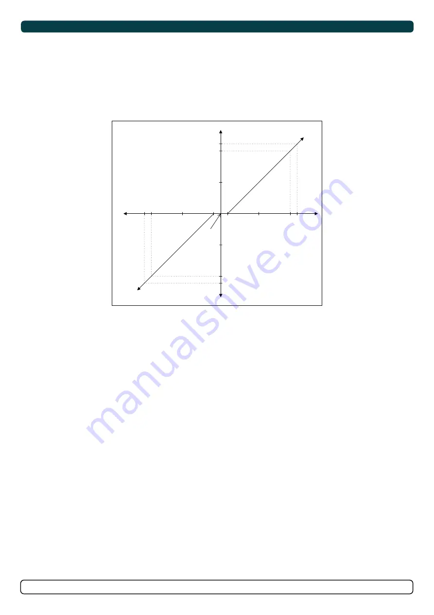
direction. 12mA is the center signal and will stop the thruster. 4mA will give 100% thrust to port side.
20mA will give 100% thrust to starboard side.
Relay output DO2 is the run enable feedback for hydraulic thrusters. DO2 will be activated when the
hydraulic thruster can run. If there is an active emergency feedback from the hydraulic controller (PHC)
then DO2 will be deactivated. DO2 have only any use with hydraulic PHC controllers.
19.
6m
A
20.
0m
A
4.
4m
A
4.
0m
A
Input signal
mA
Port Thrust in %
100% Starboard
100% Port
12.
4m
A
11.
6m
A
0%Thrust
12.0mA
Starboard Thrust in %
Содержание ESI-1
Страница 11: ...11 2920 6 2021 ESI...