


17
7240
6
2022
-
E300
MC_0528
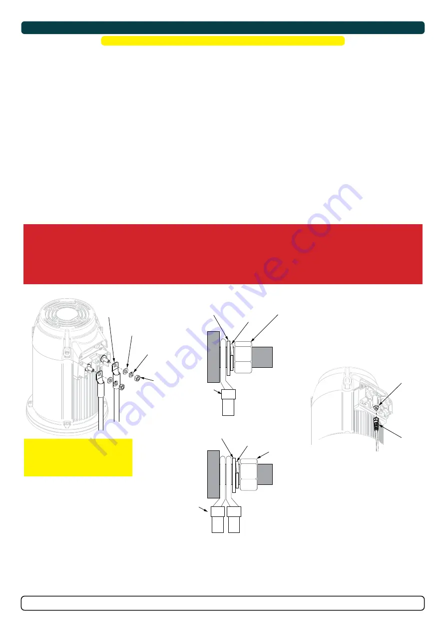
Electrical Installation
WARNING
Check the following with the main switch is set to off :
After all electrical connections have been completed check with an ohm meter that there is no electrical connection between
1. electro-motor flange and the positive terminal on the motor
2. electro-motor flange and the battery negative terminal on the motor
If unsure contact skilled personnel.
1. Information of electrical table.
see next page
- All power cable lengths represent the total length of the combined (+) and (-) cables.
- Battery capacity is stated as minimum cold crank capacity, (CCA).
- Use slow blow rated fuses to hold stated Amp-Draw for min. 5 minutes.
- Consider the AMP hours (Ah) for your specifi c duty cycle.
2. Use appropriate sized cables and batteries with high cranking capacity to feed the thruster. Use larger cables and stronger batteries for better
results.
- See electrical specifi cations for advised minimum cables and batteries (CCA).
3. Install the main switch as close to the battery as possible and ensure the main positive lead can take loads without noticeable voltage drop.
- Ensure the main switch (battery isolator) can be turned off independently and manually when not on board or in emergencies.
- Ensure it is easily accessible and update instructions that this should be turned off like the boat’s other main switches.
It is advised to install a fuse in the positive lead for protection against short-circuiting.
- Ensure a slow type and appropriately sized to take the amperage draw for at least 5 minutes.
(NB: For Ignition Protected installations remember to use ignition protected fuses and switches if fi tted in areas that require this feature.
Ensure to follow your national regulations)
5. Cable lugs must have adequate electrical and mechanical isolation and fi tted with cable lug covers.
6. Fasten cables to the required torque.
!
Please refer to the graphic for special considerations relating to your model
!
MG_0523
End nut
End nut
S-Link cable
S-Link
Connector
(M10) Nut
Tighten to *max
13 Nm (9.59 lb/ft)
Spring
washer
Spring
washer
Washer
Washer
Lugs
Lug
IMPORTANT
Do NOT use washers between lugs,
this causes overheating and fire. Spring
washers must be placed in the outer
position before tightening the nut.
Lugs
End nut
Spring
washer
Washer
Multi-lug
configuration
Ensure lug faces
are back to back.
Single-lug
configuration
Ensure lug faces
are back to back.
Motor Installation
1. Install the motor onto the motor bracket ensuring the couplings are engaged together correctly (top and bottom).
(NB: The motor can be placed
in all directions on the motor bracket. However, ensure the cable terminals are accessible for electrical installation later.)
2. If you are installing the motor at an angle of more than 30 degrees off vertical, the motor will require separate/ additional support.
(NB: Do not
position supports on the motors top cap.)
3. Fasten the bolts holding the motor to the motor bracket with the above torque.
4. Check the drive shafts are engaged by rotating the propeller.
(NB: Rotating the propellers can be hard due to the gear reduction and the motor,
however the propeller must be able to rotate via hand power.)
MC_0019
!
Please refer to the graphic for special considerations relating to your model
!
IMPORTANT
The thruster motor assembly must be protected using suitable covering to avoid dust/debris ingress from fabrication/maintenance/shipbuilding
operations. On completion of operations, the cover must be removed before operating the thruster.
MG_0571
1
2
3
FASTEN
(33 Nm)
(24 lb/ft)
Motor
Cap
> 30°
Holding Key
IMPORTANT
Ensure the holding key
and coupling are
aligned when fitted
Motor support
bracket
Motor lifting
hooks
4
Содержание E-Vision Electric Thruster E300
Страница 26: ...26 7240 6 2022 E300 MC_0037 Notes...
Страница 27: ...27 7240 6 2022 E300 MC_0037 Notes...


