21
NOTICE D'UTILISATION
P 1
BEDIENUNGSANLEITUNG
S 11
OPERATING INSTRUCTIONS
P 21
GEBRUIKSHANDLEIDING
P 31
MANUAL DE USUARIO
P 41
AES
50 W to 600 W
Страница 1: ...e 180140018Ga NDU NOT140012Ga Edition 0619 NOTICE D UTILISATION P 1 BEDIENUNGSANLEITUNG S 11 OPERATING INSTRUCTIONS P 21 GEBRUIKSHANDLEIDING P 31 MANUAL DE USUARIO P 41 NOTICE D UTILISATION AES 50W 60...
Страница 2: ...votre quipement 5 2 1 Fixation et dimensions des coffrets dim LxHxP mm 5 2 2 Batteries 6 3 Raccordement 6 3 1 Plan de raccordement 6 3 2 Sections maximum de raccordement 7 4 Mise en service 7 5 Fonct...
Страница 3: ...d alarme Incendie Partie 4 quipement d alimentation lectrique EN 12101 10 classe A 2005 Syst mes pour le contr le des fum es et de la chaleur Partie 10 quipement d alimentation en nergie NFS 61940 20...
Страница 4: ...s e 195V 264V fr quence 50 60Hz classe I r gimes de neutre TT TN IT 50W 75W 100W 150W 200W 300W 400W 600W Courant primaire 195V 0 4A 0 5A 0 75A 1A 1 5A 2A 3A 4A Disjoncteur pr voir en amont courbe D 1...
Страница 5: ...6Ah de 2 1 12Ah 200W de 7 110Ah de 4 65Ah 300W de 7 166Ah de 4 65Ah 400 600W de 12 225Ah de 4 140Ah V rifier que les batteries sont bien conformes aux normes en vigueur dans les pays o elles sont util...
Страница 6: ...e pas cr er d ouvertures suppl mentaires sous peine de dysfonctionnement de l appareil et de non reprise sous garantie sauf emplacements pr vus sur C38 et C85 Le raccordement des batteries sur les rac...
Страница 7: ...e utilisation La LED de la carte m re devient rouge 3 Fermer le fusible batterie ou raccorder les bornes de la batterie pour les cartes de 50 150W 4 V rifier le voyant de bon fonctionnement sur la car...
Страница 8: ...tension de sortie 1 signal e en local par une LED verte Pr sence tension de sortie 2 signal e en local par une LED verte Les pr sences tension de sortie 1 et 2 sont signal es distances par un contact...
Страница 9: ...vent tre mises au rebut conform ment aux obligations de recyclage des mat riaux 7 Protections fusibles 7 1 Versions 24V 24V 2A 24V 3A 24V 4A 24V 6A 24V 8A 24V 12A 24V 16A 24V 24A F1 secteur calibre ty...
Страница 10: ...er la compatibilit de votre utilisation Si la batterie ne prend pas le relais apr s un d faut secteur Contr ler la tension aux bornes de la batterie Contr ler le fusible batterie Contr ler la tension...
Страница 11: ...11 NOTICE D UTILISATION P 1 BEDIENUNGSANLEITUNG S 11 OPERATING INSTRUCTIONS P 21 GEBRUIKSHANDLEIDING P 31 MANUAL DE USUARIO P 41 BEDIENUNGSANLEITUNG AES 50 W bis 600 W...
Страница 12: ...Stromversorgung 15 2 1 Befestigung und Abmessungen der Geh usek sten Abm LxHxP mm 15 2 2 Batterien 16 3 Anschluss 16 3 1 Anschlussplan 16 3 2 Maximale Anschlussquerschnitte 17 4 Inbetriebnahme 17 5 F...
Страница 13: ...nach den Normen f r den jeweiligen Einsatzbereich zertifiziert EN 54 4 1997 A1 2002 A2 2006 Brandmeldeanlagen Teil 4 Energieversorgungseinrichtungen EN 12101 10 Klasse A 2005 Rauch und W rmefreihaltun...
Страница 14: ...60 Hz Klasse I Sternpunktbetrieb TT TN IT 50 W 75 W 100 W 150 W 200 W 300 W 400 W 600 W Prim rstrom bei 195 V 0 4 A 0 5 A 0 75 A 1 A 1 5 A 2 A 3 A 4 A Ein vorgeschalteter Trennschalter ist vorzusehen...
Страница 15: ...von 2 1 bis 12Ah 200W von 7 bis 110Ah von 4 bis 65Ah 300W von 7 bis 166Ah von 4 bis 65Ah 400 600W von 12 bis 225Ah von 4 bis 140Ah Pr fen dass die Batterien gut mit den g ltigen Normen in den L ndern...
Страница 16: ...zum Ausfall des Ger ts und Verlust der Garantie f hren Ausgenommen sind die in den C38 und C85 Geh usen vorgestanzten ffnungen Der Anschluss von Batterien an F3U 3U Racks erfordert die Verwendung von...
Страница 17: ...emmen wieder an 4 Pr fen Sie ob die Kontrollleuchte auf der Hauptplatine den ordnungsgem en Betrieb anzeigt o alles OK gr n o Netzst rung orange o St rung Batterie oder Ladeger t oder Abwesen der Ausg...
Страница 18: ...sgang 2 Wird lokal ber eine gr ne LED angezeigt Das Anliegen von Spannung an den Ausg ngen 1 und 2 wird fern ber einen potenzialfreien NO NC Kontakt selbstsicher angezeigt 5 2 Zusammenfassung der verf...
Страница 19: ...Sicherungen 7 1 Version 24 V 24 V 2 A 24 V 3 A 24 V 4 A 24 V 6 A 24 V 8 A 24 V 12 A 24 V 16 A 24 V 24 A F1 Netz Sicherungseinsatz typ Gr e Abschaltverm gen 3 15 A T 5x20 1500 A 2 A T 5x20 1500 A 6 3 A...
Страница 20: ...tterie nach einer Netzst rung nicht ihre Aufgabe bernimmt Kontrollieren Sie die Spannung an den Batterieklemmen Kontrollieren Sie die Batteriesicherung Kontrollieren Sie die Spannung an den Klemmen Ve...
Страница 21: ...21 NOTICE D UTILISATION P 1 BEDIENUNGSANLEITUNG S 11 OPERATING INSTRUCTIONS P 21 GEBRUIKSHANDLEIDING P 31 MANUAL DE USUARIO P 41 OPERATING INSTRUCTIONS AES 50 W to 600 W...
Страница 22: ...tion of your equipment 25 2 1 Mounting and cabinet dimensions dim LxHxW mm 25 2 2 Batteries 26 3 Connection 26 3 1 Connection diagram 26 3 2 Maximum connection sizes 27 4 Commissioning 27 5 AES Operat...
Страница 23: ...1997 A1 2002 A2 2006 Fire detection and fire alarm systems Part 4 power supply equipment EN 12101 10 class A 2005 Smoke and heat control systems Part 10 power supplies NFS 61940 2000 Fire Safety Syst...
Страница 24: ...frequency 50 to 60 Hz class I neutral systems TT TN IT 50 W 75 W 100 W 150 W 200 W 300 W 400 W 600 W Primary current 195 V 0 4 A 0 5 A 0 75 A 1 A 1 5 A 2 A 3 A 4 A Circuit breaker to be provided upst...
Страница 25: ...1 to 12Ah 200W 7 to 110Ah 4 to 65Ah 300W 7 to 166Ah 4 to 65Ah 400 600W 12 to 225Ah 4 to 140Ah Check that the batteries are in conformity with the standards effective in the countries where they are us...
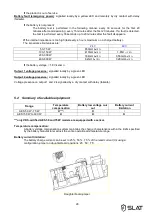
Страница 26: ...ot create additional openings as doing so may casue the device to malfunction and voids the warranty except locations on C38 and C85 The connection of batteries on F3U 3U racks requires the use of cab...
Страница 27: ...e load output voltage The LED on the motherboard turns red 3 Close the battery fuse or connect the battery terminals for 50 W to 150 W boards 4 Check that the LED confirming correct motherboard operat...
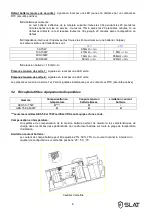
Страница 28: ...8m 10 If the battery voltage 1 8 V cell 5 Output 1 voltage presence signalled locally by a green LED Output 2 voltage presence signalled locally by a green LED Voltage presence on output 1 and 2 is si...
Страница 29: ...ons 7 1 24 V versions 24 V 2 A 24 V 3 A 24 V 4 A 24 V 6 A 24 V 8 A 24 V 12 A 24 V 16 A 24 V 24 A F1 mains rating type size breaking capacity 3 15 A Time lag 5x20 1500 A 2 A Time lag 5x20 1500 A 6 3 A...
Страница 30: ...e validated check the compatibility of your load If the battery does not take over after a mains fault Check the voltage on the battery terminals Check the battery fuse Check the voltage on terminals...
Страница 31: ...31 NOTICE D UTILISATION P 1 BEDIENUNGSANLEITUNG S 11 OPERATING INSTRUCTIONS P 21 GEBRUIKSHANDLEIDING P 31 MANUAL DE USUARIO P 41 GEBRUIKSHANDLEIDING AES 50W tot 600W...
Страница 32: ...Bevestigingselementen en afmetingen van de kasten afm LXHXD mm 35 2 2 Accu s 36 3 Aansluitingen 36 3 1 Aansluitschema 36 3 2 Maximum kabeldikte aansluitingen 37 4 Ingebruikneming 37 5 Bediening van d...
Страница 33: ...men EN 54 4 1997 A1 2002 A2 2006 Branddetectiesystemen Deel 4 installatie voor elektrische voeding EN 12101 10 Klasse A 2005 Systemen voor het controleren van rook en hitte Deel 10 installatie voor el...
Страница 34: ...tot 264V frequentie 50 tot 60Hz klasse I sterpuntsschakelingen TT TN IT 50W 75W 100W 150W 200W 300W 400W 600W Primaire stroom 195V 0 4A 0 5A 0 75A 1A 1 5A 2A 3A 4A Stroomopwaarts te monteren different...
Страница 35: ...200W van 7 tot 110Ah van 4 tot 65Ah 300W van 7 tot 166Ah van 4 tot 65Ah 400 600W van 12 tot 225Ah van 4 tot 140Ah Controleren dat de batterijen zeer in overeenstemming met de normen geldend in de land...
Страница 36: ...paraat en omdat de garantie hierdoor vervalt Behalve locaties op C38 en C85 Voor het aansluiten van batterijen op F3U 3U rekken zijn kabels met een lengte van minder dan 3m nodig Tabel voor het gebrui...
Страница 37: ...aart wordt rood 3 Sluit de accuzekering of sluit de accuklemmen aan voor de kaarten van 50 tot 150W 4 Controleer de goede werking van de LED op de moederkaart o alles ok groen o storing netspanning or...
Страница 38: ...g 1 en 2 worden op afstand aangegeven door een potentiaalvrij contact failsafe 5 2 Overzicht van verkrijgbare accessoires Gamma Temperatuurcompensatie Accu afschakeling bij minimale accuspanning Accul...
Страница 39: ...gG 10 3x38 32A gG 10 3x38 7 2 Versies 48V 48V 2A 48V 3A 48V 4A 48V 6A 48V 8A 48V 12A F1 netspanning kaliber type maat breeksterkte 2A T 5x20 1500A 6 3A T 5x20 1500A 8A T 5x20 1500A F7 F8 uitgangsspann...
Страница 40: ...nsluiting van de accu en de zekering van de accu controleren Controleer of de vlakbandkabel goed is aangesloten Controleer de spanning op de aansluitklemmen uitgangsspanning 1 en of uitgangsspanning 2...
Страница 41: ...41 NOTICE D UTILISATION P 1 BEDIENUNGSANLEITUNG S 11 OPERATING INSTRUCTIONS P 21 GEBRUIKSHANDLEIDING P 31 MANUAL DE USUARIO P 41 MANUAL DE USUARIO AES de 50 a 600 W...
Страница 42: ...Fijaci n y dimensiones de las cajas LxAxP en mm 45 2 2 Bater as 46 3 Conexi n 46 3 1 Esquema de conexiones 46 3 2 Secciones m ximas de las conexiones 47 4 Puesta en funcionamiento 47 5 Funcionamiento...
Страница 43: ...pos de suministro de alimentaci n EN 12101 10 clase A 2005 Sistemas para el control de humo y de calor Parte 10 Equipos de suministro de energ a NFS 61940 2000 Fuentes de alimentaci n el ctrica de seg...
Страница 44: ...V Frecuencia de 50 a 60 Hz Clase I Reg menes de neutro TT TN IT 50 W 75 W 100 W 150 W 200 W 300 W 400 W 600 W Corriente primaria a 195 V 0 4 A 0 5 A 0 75 A 1 A 1 5 A 2 A 3 A 4 A Disyuntor de entrada...
Страница 45: ...12Ah 150W 7 86Ah 2 1 12Ah 200W 7 110Ah 4 65Ah 300W 7 166Ah 4 65Ah 400 600W 12 225Ah 4 140Ah Comprobar que las bater as se ajustan bien a las normas vigentes en los pa ses donde se utilizan 2 Instalac...
Страница 46: ...jas No deben realizarse orificios nuevos puesto que podr a provocar un funcionamiento an malo del aparato y quedar a anulada la garant a excepto ubicaciones para los C38 y C85 La conexi n de las bater...
Страница 47: ...es de la bater a para las tarjetas de 50 a 150 W 4 En la placa base comprobar el piloto que indica si el funcionamiento es correcto o Todo correcto verde o Fallo red naranja o Fallo en bater a o carga...
Страница 48: ...a tensi n de salida 2 fuente normal sustituci n Se indica localmente mediante un LED verde Las presencias de tensi n de salida 1 y 2 se indican a distancia mediante un contacto seco NC NO seguridad po...
Страница 49: ...5x20 12 5 A time lag 5x20 25 A gG 10 3x38 FBat bater a calibre tipo tama o Fusible de rearme autom tico 16 A gG 10 3x38 32 A gG 10 3x38 7 2 Versiones 48 V 48 V 2 A 48 V 3 A 48 V 4 A 48 V 6 A 48 V 8 A...
Страница 50: ...robar la conexi n de la bater a el fusible de la misma Comprobar que el cable plano est bien conectado Comprobar la tensi n en los bornes util 1 y o util 2 Si necesita asistencia t cnica adicional lla...
Страница 51: ...3 2008 AES 48V 2A C24 SB 0333 CPR 075187 2008 AES 48V 2A C38 SB 0333 CPR 075190 2008 AES 48V 3A C38 SB 0333 CPR 075191 2008 AES 48V 3A F3U 0333 CPR 075195 2008 AES 200 300W AES 24V 8A C48 SB 0333 CPR...
Страница 52: ...BP66 69543 CHAMPAGNE AU MONT D OR Cedex France Tel 33 0 4 78 66 63 60 E mail comm slat fr SLAT GmbH Leitzstra e 45 70469 Stuttgart Deutschland Tel 49 0 711 899 890 08 Fax 49 0 711 899 890 90 E mail in...