louvered opening near the ceiling, each opening with a
minimum FREE air passage area of 550 mm
2
per kW (1
square inch per 4000 BTUH) of total appliances’ input.
2. Air drawn horizontally through HORIZONTAL DUCTS; one
opening near the floor and one opening near the ceiling,
each opening with a minimum FREE air passage area of
1100 mm
2
per kW (1 square inch per 2000 BTUH) of total
appliances’ input.
3. Air drawn VERTICALLY from outdoors; one opening at the
floor and one opening at the ceiling, each opening with a
minimum FREE air passage area of 550 mm
2
per kW (1
square inch per 4000 BTUH) of total appliances’ input.
4. Air drawn from inside the building; one opening near the
floor and one opening near the ceiling, each opening with
a minimum FREE air passage area of 2200 mm
2
per kW
(1 square inch per 1000 BTUH) of total appliances’ input.
IF BOILERS ARE INSTALLED ADJACENT TO OTHER FUEL
BURNING EQUIPMENT, THE AREA OF FREE OPENINGS
MUST BE APPROPRIATELY INCREASED TO ACCOM MO -
DATE THE ADDITIONAL LOAD.
B. DIRECT VENT INSTALLATION
Adequate air supply should be provided to prevent over -
heating of the boiler controls and boiler room. Openings for
passage of air into the boiler room for direct-vent installation
must be at least 1/2 of the openings required for the non-
direct vent as mentioned above.
If additional non-direct vent appliances are installed in the
same space and adequate air openings are provided for
them, there are no additional air openings required for the
Lynx LX-85.
For both direct and non-direct installation, the following must
be considered:
- Openings must never be reduced or closed. If doors or
windows are used for air supply, they must be locked
open.
-
Protect against closure of openings by snow and debris.
Inspect frequently.
-
No mechanical draft exhaust or supply fans are to be used
in or near the boiler area.
-
Boiler area must never be under negative pressure. The
flow of combustion and ventilating air to the boiler must
not be obstructed.
FLUE GAS VENTING REQUIREMENTS
The Lynx LX-85 series boiler is a high efficiency, mechanically
forced draft boiler and, therefore, requires different venting
arrangements than natural draft, lower efficiency boilers.
THE FOLLOWING INSTRUCTIONS MUST BE CAREFULLY
READ AND FOLLOWED IN ORDER TO AVOID ANY
HAZARDOUS CONDITIONS DUE TO IMPROPER
INSTALLATION OF THE AIR INTAKE AND FLUE GAS
VENTING SYSTEM.
The vent piping installation MUST be in accordance with
these instructions and with ANSI Z223.1-latest edition, and
CSA B149.1-00. Other local codes may also apply and must
be followed. Where there is a conflict between these
requirements, the more stringent case shall apply. The use of
a vent damper is NOT permitted on this boiler series.
VENT AND AIR INTAKE MATERIALS
The vent piping for direct or non-direct vent installation must
be 76mm (3") diameter Certified PVC or CPVC Venting, or UL
listed single wall 76mm (3") diameter AL29-4C* stainless steel
material. The air intake piping for direct vent installation must
be 76mm (3") diameter PVC/CPVC schedule 40 pipe. The
following manufacturers’ systems are approved for use within
a specified minimum and maximum equivalent vent length in
this manual.
When joining the various components of the listed stainless
steel vent systems or Certified PVC or CPVC Venting
Systems, the manufacturers’ instructions should be closely
followed to insure proper sealing. Use sealant specified by
vent system manufacturer for sealing of pipe and fittings, if
required. When joining the Certified PVC or CPVC Venting
pipe and fittings (for air intake only), follow the instructions
provided in this manual. All connections must be liquid and
pressure tight.
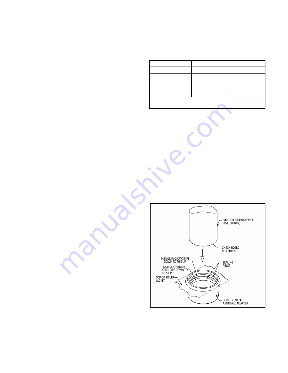
The integral adapters on the boiler are designed to accommo-
date either PVC/CPVC Schedule 40 pipe or the listed stainless
steel vent systems. These adapters have built-in sealing rings,
so no additional sealant is required. Make sure the pipes are
round and burr-free, and push down into the appropriate step
of the adapter, until snug. (See Figure 5). Apply liquid soap to
the outer end of the vent pipe and air intake pipe for easy
insertion.
FOR AIR INTAKE ONLY:
PVC/CPVC PIPE GENERAL ASSEMBLY METHOD
The following are the recommended methods for cutting,
cleaning and connecting PVC and CPVC pipe, for the air
intake piping system:
Lynx Model LX-85A
6
Figure 5. Vent and Air Intake Pipe installation into Boiler
vent and air intake connections.
Manufacturer
Type/System
Sealant
Heat-Fab. Inc.
Saf-T Vent EZ Seal
Not Required
ProTech System, Inc.
FasNSeal
Not Required
Flex-L International, Inc.
StaR-34
GE-IS806
Z-Flex, Inc.
Z-Vent
GE, RTV 106
Certified PVC or CPVC Venting Systems Certifed to ULC
S636
Содержание LX-85A
Страница 19: ...Lynx Model LX 85A 19 Figure 16a Schematic wiring diagram...
Страница 20: ...Lynx Model LX 85A 20 Figure 16b Boiler Control Figure 16c Ladder wiring diagram...
Страница 22: ...Lynx Model LX 85A 22 Figure 17c Multizoning of Lynx boiler pump zoning system using R882A B relays...
Страница 43: ...Lynx Model LX 85A 43...


