background image

Industrial Power Supplies

Single Output 1500 Watt

TF1500 Family

TF1500 Application Note v1019

Copyright © 2019 SL Power Electronics Corp. All rights reserved.

Page 12

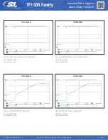
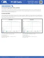
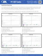
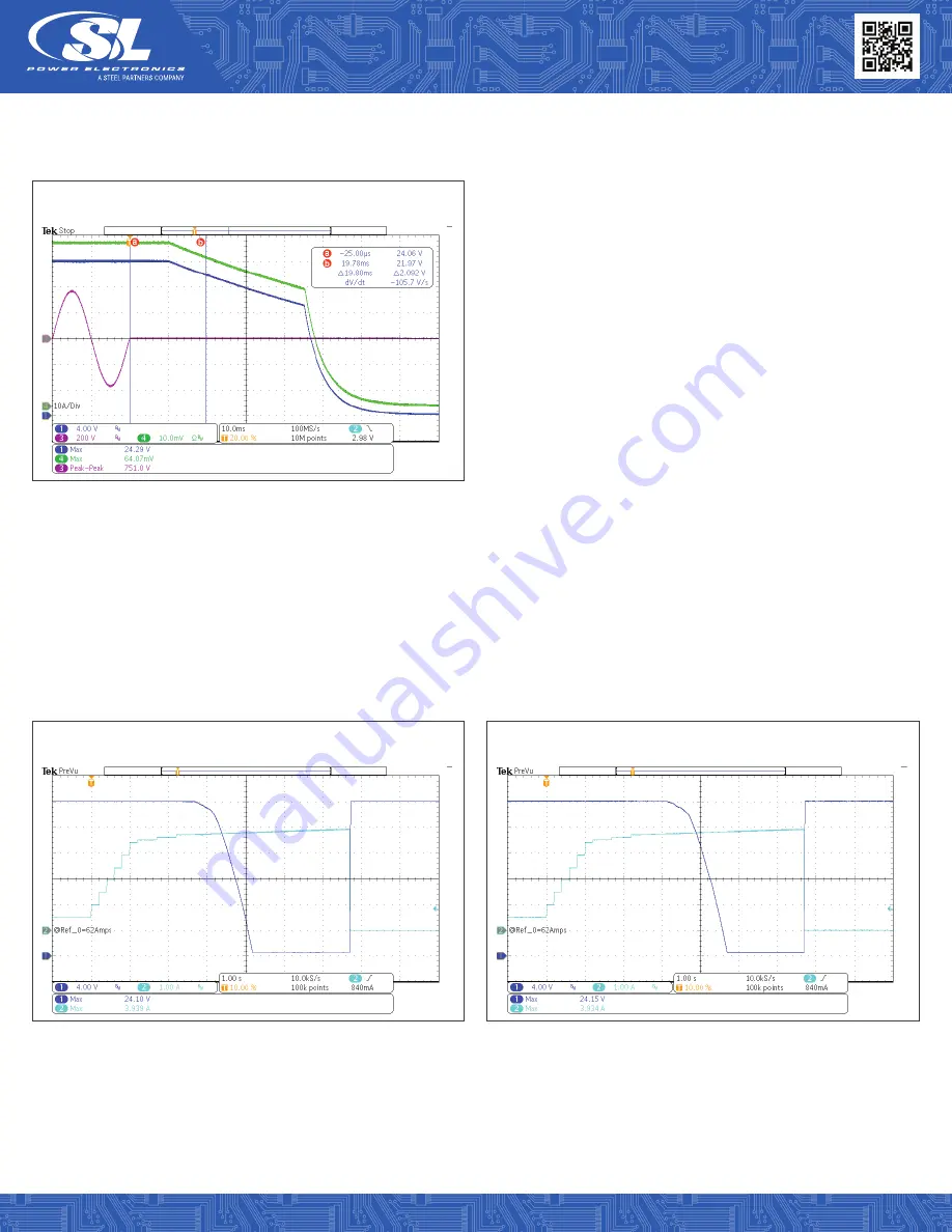
Fig. 20: HOLD-UP TIME AT 264VAC 100% CRM.
CH1: Output Voltage.

CH3: Input Voltage.

CH4: Output Current.

TF1500A24K01

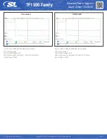
Fig. 21: OUTPUT OVERLOAD AT 115VAC CCM.
CH1: Output Voltage.

CH4: Output Current.

CH1: Output Voltage.

CH4: Output Current.

Fig. 22: OUTPUT OVERLOAD AT 230VAC CCM.

TF1500A24K01

TF1500A24K01

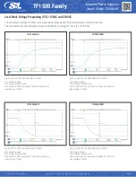
Overload Protection 115VAC and 230VAC
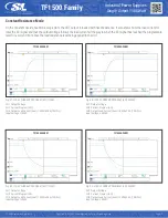
Constant Current Mode

For better visualization the power supply unit was preloaded with current of 62A.

Содержание TF1500 Series

Страница 1: ...Page 1 TF1500 Application Note v1019 Copyright 2019 SL Power Electronics Corp All rights reserved TF1500 Family Industrial Power Supplies Single Output 1500 Watt AN P026...

Страница 2: ...host PC or for quick indication an intelligent 3 color LED reports the global status of the unit such as power OK in remote or local mode standby failure signals for overvoltage overcurrent or overte...

Страница 3: ...comes by default with jumpers on local sense pins VS and VS to corresponding output pins VO and VO To use remote sense feature remove these jumpers and connect VS VS pins with wires to the load where...

Страница 4: ...ection TF1500 series power supply offer mounting options from the bottom and or long sides of enclosure Refer to the mechanical drawing in the datasheet for detailed dimensions Use M4 screws with maxi...

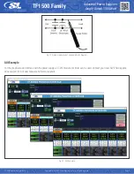
Страница 5: ...wer Electronics Corp All rights reserved Page 5 Fig 01 Noise measurement caps and probe diagram GUI Example For the graphical user interface with the power supply a CT 251 module or similar can be use...

Страница 6: ...controller Therefore the possible readout of output voltage and output current are limited approximately to one decimal digit For example while reading with the tool the output voltage of 50 23V it wi...

Страница 7: ...r Electronics Corp All rights reserved Page 7 PERFORMANCE DATA The following data is provided to aid in proper selection and system design of TF1500A24K Additional performance data is available upon r...

Страница 8: ...AT 115VAC 100 Fig 08 INRUSH CURRENT AT 230VAC 100 TF1500A24K01 TF1500A24K01 TF1500A24K01 TF1500A24K01 AC Inrush Current 115VAC and 230VAC for 24V The AC input inrush current cold start power on is sho...

Страница 9: ...A24K01 TF1500A24K01 TF1500A24K01 Turn On Delay Time 115VAC and 230VAC Constant Current Mode At start up a load current oscillation at near zero output voltage can occur This anomaly is observed with e...

Страница 10: ...t Current Fig 14 TURN ON RISE TIME AT 230VAC 100 CRM TF1500A24K01 TF1500A24K01 Output Turn On Rise Time 115VAC and 230VAC No Load Full Load Constant Resistance Mode Fig 15 HOLD UP TIME AT 115VAC 100 C...

Страница 11: ...0A24K01 Output Hold Up Time 115VAC 230VAC 264VAC Constant Current Mode time to Vout drops to 90 rated Note Load current oscillation during turn off at near zero output voltage is an anomaly of the con...

Страница 12: ...100 CRM CH1 Output Voltage CH3 Input Voltage CH4 Output Current TF1500A24K01 Fig 21 OUTPUT OVERLOAD AT 115VAC CCM CH1 Output Voltage CH4 Output Current CH1 Output Voltage CH4 Output Current Fig 22 OUT...

Страница 13: ...Output Voltage CH4 Output Current CH1 Output Voltage CH4 Output Current Fig 24 SHORT CIRCUIT INITIAL EVENT AT 230VAC CRM TF1500A24K01 TF1500A24K01 Constant Resistance Mode Short Circuit Protection 11...

Страница 14: ...e 14 Fig 27 SHORT CIRCUIT NO HCC UP 115VAC 100 CH1 Output Voltage CH4 Output Current CH1 Output Voltage CH4 Output Current Fig 28 SHORT CIRCUIT NO HCC UP 230VAC 100 TF1500A24K01 TF1500A24K01 Fig 29 SH...

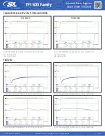
Страница 15: ...STEP LOAD Fig 35 TRANSIENT RESPONSE AT 115VAC 10 50 STEP LOAD Fig 34 TRANSIENT RESPONSE AT 230VAC 10 50 STEP LOAD Fig 36 TRANSIENT RESPONSE AT 230VAC 10 50 STEP LOAD Transient Response 10 50 115VAC a...

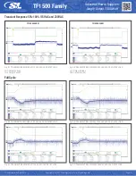
Страница 16: ...ig 37 TRANSIENT RESPONSE AT 115VAC 50 100 STEP LOAD Fig 39 TRANSIENT RESPONSE AT 115VAC 50 100 STEP LOAD Fig 41 TRANSIENT RESPONSE AT 115VAC 50 100 STEP LOAD CH1 Output Voltage CH4 Output Current CH1...

Страница 17: ...1 SIGNAL WAVEFORMS Local Current Program ACI 115VAC and 230VAC The Local Mode Current Program ACI signal was monotonically controlled using an external DC source This external source was remotely volt...

Страница 18: ...eserved Page 18 Fig 45 LOCAL CURRENT PROGRAM ACI 115VAC CH1 Output Voltage CH2 Current Program ACI CH4 Output Load Current Aout 1 5KW 62 5A 10A Div Input Voltage 115VAC CH1 Output Voltage CH2 Current...

Страница 19: ...ant Resistance Mode On the Constant Resistance Mode scope plots the UUT output is loaded with fixed resistance It also shows how the load current fol lows the ACI signal and that the output voltage fo...

Страница 20: ...ig 52 LOCAL VOLTS PROGRAM ACI 230VAC TF1500A24K01 TF1500A24K01 Local Mode Voltage Programing VCI 115VAC and 230VAC The Local Mode Voltage Program VCI signal was monotonically controlled using an exter...

Страница 21: ...EN Hi Vout Off 230VAC TF1500A24K01 TF1500A24K01 Inhibit EN EN 115VAC and 230VAC The remote ON OFF control inhibit was tested using the auxiliary power source AUX and a toggle switch for either end of...

Страница 22: ...oltage CH2 Inhibit On Off EN CH3 Input AC Line Voltage CH4 Output Load Current Aout 840W 35A 10A Div Input Voltage 230VAC Fig 60 INHIBIT EN Hi Vout On 230VAC TF1500A24K01 TF1500A24K01 Fig 61 INHIBIT E...

Страница 23: ...CH3 Aux Output Voltage Vaux or Aux CH4 Output Load Current Aout 840W 35A 10A Div Input Voltage 230VAC Fig 64 Vset Hi Lo Vaux 5V 9V 115VAC TF1500A24K01 TF1500A24K01 Auxiliary Power and Setting AUX SET...

Страница 24: ...POWER OK POK 115VAC 840W CH1 Output Voltage CH2 Power OK Signal POK CH3 Input AC Line Voltage CH4 Output Load Current Aout 840W 35A 10A Div Input Voltage 115VAC CH1 Output Voltage CH2 Power OK Signal...

Страница 25: ...UUT 2 Output Load Current A2out 10A Div CH4 UUT 1 Output Load Current A1out 10A Div Input Voltage 115VAC CH1 Output Voltage Offset 10V CH2 Parallel Current Share PAR CH3 UUT 2 Output Load Current A2o...

Страница 26: ...output and earth ground or chassis ground This comes about due to parasitic capacitance and inductive coupling in the power supply that couple electrical energy from the primary to the secondary or fr...

Страница 27: ...CE Quasi Peak Average 100 Load 240V 60Hz Line Conducted Emission EMI Plots were collected at 10 and 100 loads 120VAC 60Hz and 240VAC 50Hz The Curves are Quasi peak QP and Average mea surements The QP...

Страница 28: ...v1019 Copyright 2019 SL Power Electronics Corp All rights reserved Page 28 Fig 81 CE Quasi Peak Average 10 Load 120V 60Hz Line Fig 82 CE Quasi Peak Average 10 Load 240V 60Hz Line Fig 83 CE Quasi Peak...

Страница 29: ...rience Center Applications Engineering Test Facility 6 Merchant Street Suite 2 Sharon MA 02067 Phone 800 235 5929 Fax 805 832 6135 Email info slpower com Europe EMEA Regional Office Sales Support Unit...

Отзывы: