

40
41
PART XII : USING A SYNSCAN GPS MODULE
12.1 Initialization of the Hand control with a SynScan GPS Module
12.2 Checking GPS Information
3.
The hand control will then ask the user whether to use the Daylight Saving Time. Use the
scroll keys to select between “
YES
” and “
NO
” and press the
ENTER
key to confirm and pro
-
ceed.
4.
The screen will now display “
GPS fixing…
”. It means that the GPS module is trying to fix to
the GPS satellites.
5.
After the SynScan GPS module fixes to the satellites, the SynScan hand control will
con-
tinue the initialization process.
1.
Plug the SynScan GPS module into the multi-purpose port (the 6 pins RJ-12 port) located
at the bottom center of the SynScan hand control. Place the GPS module on a horizontal
surface.
2.
Access the menu “
UTILITY FUNCTION \ GPS
” in the menu and press the
ENTER
key.
3.
The screen will now display “
GPS fixing…
”. It means that the GPS module is trying to fix to
the GPS satellites.
4.
After the SynScan GPS module fixes to the satellites, the screen will display “
GPS Infor-
mation:
”. Use scroll keys to browse through the following information. Press the
ESC
key
to exit.
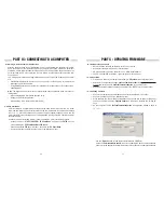
•
Use the left and right direction keys to move the cursor on the screen.
•
Use the scroll keys to change or switch the sign for the time zone. Use “
+
” for the time
zones in the Eastern Hemisphere, use “
-
” for the time zones in the Western Hemi-
sphere.
• Use the numeric keys to fill the time zone value in
±hh:mm
format.
•
Press
ENTER
to confirm and proceed.
•
M.O.V:
Local magnetic declination
•
Lat:
Local latitude
•
Lo:
Local longitude
•
Date
: Local date
•
UT:
Greenwich Mean Time
•
LT:
Local time
•
TimeZone:
Local time zone
•
LST:
Local sidereal time
•
Elevation:
Local elevation
•
Quality:
Quality of GPS fixing
•
Number of SV:
Number of GPS satellites in view
•
SV(fix) Nr:
Number of GPS satellites fixed
The initialization process of the SynScan hand control with a SynScan GPS plug-in differs
from a regular one.
1.
Plug the SynScan GPS module into the multi-purpose port (the 6 pins RJ-12 port) located
at the bottom center of the SynScan hand control. Place the GPS module on a horizontal
surface and turn on the power of the mount.
2.
If the SynScan hand control detects the connection of a GPS module, it will ask for the
local time zone:
Users may purchase a SynScan GPS module to acquire accurate local geographical coordi-
nates and local time; it will help improve the accuracy of the mount alignment and the polar
alignment.
Testing for Cone Error
Eliminating Cone Error
APPENDIX I : ELIMINATING CONE ERROR
•
If the pointing accuracy is still good, then the mount system has small or no cone error.
•
If the pointing accuracy becomes poor, and most of the error is on the R.A. axis (that is,
the object can be brought back to the center of the eyepiece using the left or right di-
rection keys), it means that the cone error of the telescope-mount system is quite large.
If the telescope’s optical axis is not perpendicular to the declination axis of the equatorial
mount, then there is cone error in the telescope-mount system. The cone error might lower the
accuracy of locating an object or the accuracy of the Polar-Alignment process.
1.
Perform a precise polar alignment on the equatorial mount, and then perform a two-star
alignment. The alignment stars should be located on the same side of the meridian and
their declination deviation should be within 10 to 30 degrees.
2.
Use the SynScan hand control to locate a few objects on the same side of the meridian as
the alignment stars. The pointing accuracy should be quite good.
3.
Use the SynScan hand control to locate a few objects on the other side of the meridian as
the alignment stars.
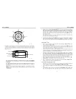
1.
Rotate the R.A. axis to level the counterweight shaft.
2.
Center the Polaris in the polar scope.
3.
Point the telescope to the Polaris, rotate the Dec. axis to bring the Polaris as close as pos-
sible to the center of the finder scope or the telescope’s eyepiece.
4.
Fine tune the azimuth and latitude of the mount to center the Polaris in the telescope’s
eyepiece.
5.
Rotate the R.A. axis 180 degrees. (the counterweight shaft should be leveled and pointed
to the other side of the mount). If the Polaris can be put to the center of the eyepiece by
rotating the Dec. axis only, it means the cone error is small and no further adjustment is
needed; otherwise, continue to the following steps.
6.
Rotate the Dec. axis to bring the Polaris as close as possible to the center of the finder
scope or the telescope’s eyepiece.
7.
Slightly push the eyepiece end of the telescope in a HORIZONTAL direction while looking
into the eyepiece, find the direction which will bring the Polaris closer to the center of the
eyepiece. In this way, a user can determine the direction in which he/she should re-position
the telescope on the saddle or the mounting bar to reduce the cone error.
8.
Use a shim (or other method) on the proper side of the saddle or the mounting bar to raise
the telescope. Look into the eyepiece while applying the shim. Reduce the deviation be-
tween the Polaris and center of the eyepiece to HALF.
9.
Repeat
Steps 4 and 5
to check whether the cone error is acceptable, repeat
Steps 6, 7 and
8
if necessary.
Tips:
•
It is recommended to use a reticle eyepiece and align the track of the Dec. movement with
one of the lines of the reticle.
•
This adjustment can be done in day time by using a distant point object to replace the
Polaris.
Содержание EQ5
Страница 1: ...INSTRUCTION MANUAL Telescopes with NEQ3 EQ5 Mount 031007V3 ...
Страница 14: ......
Страница 27: ......
Страница 29: ...INSTRUCTION MANUAL SynScan TM 140303V4 Copyright Sky Watcher ...
Страница 51: ...SynScan TM ...