


SkyTrac Systems Ltd.
Document Rev. 01.020
DOC0334
Page 29 of 49
Restricted Proprietary and Confidential Information
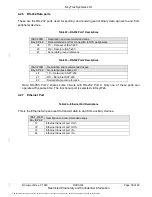
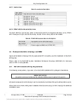
4.2.4 Current Sinking Digital Outputs
The digital outputs provide an open circuit when de-activated and a ground connection when
activated.
Table 19
—Current Sinking Digital Outputs Descriptions
ISAT-200R
Description and Recommended Usage
Pin #
Bay A
Bay B
12
Digital Output 1. Recommended to be used as an external ring
indicator.
54
Digital Output 2. Recommended for general use.
55
Digital Output 3. Recommended for general use.
53
Digital Output 4. Recommended for general use.
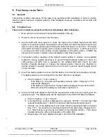
4.2.5 RS-485 Data ports
These are the RS-485 two-wire, half-duplex, multipoint serial communication channels used to
transfer data to and from auxiliary devices. These lines are used to communicate with the peripheral
devices such as the CDU-300.
Table 20
—RS-485 Port 1 Descriptions
ISAT-200R
Description and recommended usage
Bay A Pin #
Recommended port for connection to STS peripherals.
23
RS-485-A Non Inverted Input/Output Line
24
RS-485-B Inverted Input/Output Line
29
RS-485 ground reference
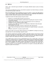
Table 21
—RS-485 Port 2 Descriptions
ISAT-200R
Description and recommended usage
Bay B Pin #
General purpose data port
43
RS-485-A Non Inverted Input/Output Line
29
RS-485-B Inverted Input/Output Line
81
RS-485-Y Non-inverted Output (4 wire mode)*
82
RS-485-Z Inverted Output (4 wire mode)*
42
RS-485 ground reference*
Note: RS-485 Port 2 shares some circuits with RS-232 Port 2. Only one of these ports can
operate at the same time. The functional port is selected via SkyWeb.
Note: RS-485 4 wire mode is only available on ISAT-200R P/N: 101-200-03
Note : RS-485_GND is isolated within the ISAT-200 system. RS-485_GND needs to be
connected to aircraft ground for reliable operation of the RS-485 databus.
The document reference is online, please check the correspondence between the online documentation and the printed version.