SkyTrac Systems Ltd.
Document Rev. 01.020
DOC0334
Page 26 of 49
Restricted Proprietary and Confidential Information
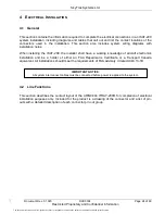
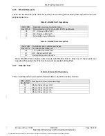
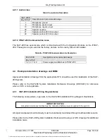
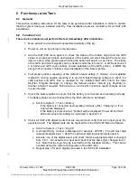
Table 15
— ARINC 404 Bay B: pin descriptions
ARINC Pin # Pin Names
Description
1
RESERVED
Microphone Ground
2
Microphone In positive line
3
RESERVED
Microphone Ground
4
CH_GND
Chassis Ground
13
MIC_IN-
Microphone In negative line
14
RESERVED
Reserved, do no connect
15
GND
Analogue Ground
16
CH_GND
Chassis Ground
26
SPKR_GND
Speaker Ground
27
SPKR_600
Speaker 600
28
SPKR_300
Speaker 300
29
RS-485_B2
RS485 port 2 inverted line
30
CH_GND
Chassis Ground Ethernet
31
ETH IN-
Ethernet negative receive port
32-39
RESERVED
Reserved, do not connect
40
DI3
Digital Input 3
41
DIO_GND
Digital I/O Ground
42
RS485_GND2** RS485 port 2 ground reference
43
RS-485_A2
RS485 port 2 non-inverted line
44
ETH IN+
Ethernet positive receive port
45-52
RESERVED
Reserved, do not connect
53
DO4
Digital Output 4
54
DO2
Digital Output 2
55
DO3
Digital Output 3
56
DI5
Digital Input 5
57
ETH OUT-
Ethernet negative transmit port
58-66
RESERVED
Reserved, do not connect
67
ADC2
Analogue Input 2 (Reserved. Do not use.)
68
ADC3
Analogue Input 3 (Reserved. Do not use.)
69
ADC4
Analogue Input 4
70
ETH OUT+
Ethernet positive transmit port
71-79
RESERVED
Reserved, do not connect
80
ADC5
Analogue Input 5
81
RS-485_Y2*
RS485 port 2 non-inverted line (4 wire mode)*
82
RS-485_Z2*
RS485 port 2 inverted line (4 wire mode)*
83-106
RESERVED
Reserved, do not connect
* RS485 4 Wire Mode is only available on ISAT-200R P/N: 101-200-03
** RS-485_GND2 is isolated within the ISAT-200 system. RS-485_GND2 needs to be connected to
aircraft ground for reliable operation of the RS-485 databus.
The document reference is online, please check the correspondence between the online documentation and the printed version.

