


REV. 3-19-20 Page 4
Skytech: RCTS-MLT-IV
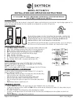
INSTALLING FLAME CONTROL SOLENOID
ALL STEPS REQUIRED FOR INSTALLATION OF THE FLAME CONTROLLER MUST BE DONE BY
A QUALIFIED GAS SERVICE TECHNICIAN
1. Using a flathead screwdriver, remove and set aside the three pressure
regulator mounting screws (A), pressure regulator tower (B), and spring
diaphragm assembly (C) and keep them in a safe place. (See Figure 1)
2. Ensure the rubber gasket (D), which is pre-fitted as part of the assembly
(E), is properly positioned and install the new pressure regulator tower
using the supplied screws (F). Tighten screws securely and remove cover
screw (G). (See Figure 1)
3. LP INSTALLATIONS ONLY: Mark the location of the slot in the slotted nut
under cover screw (G). Using a flathead screwdriver, turn the slotted nut
exactly 2 full turns (720 degrees) clockwise.
4. Insert the correct color plunger into the flame control solenoid (BLUE = NG
GAS, RED = LP GAS). (See Figure 2)
5. Ensure that the Flame Control Solenoid is disconnected from the remote
receiver box.
6. Screw the Solenoid on the to new regulator tower until it stops turning.
Then tighten the jam nut. (See Figure 2)
7. Now take the orange wire leads (connected to the solenoid) and attach
them to the orange wires (on the receiver). (See Figure 3)
CAUTION
TO ENSURE SAFE OPERATION, THE OUTLET PRESSURES ON BOTH
REGULAR AND HI FLAME LEVELS SHOULD BE CHECKED WITH A
MANOMETER IN ACCORDANCE WITH SPECIFICATIONS SUPPLIED BY
THE VALVE MANUFACTURER.
FIGURE #1
•
Slide the 3-position button on the remote receiver to the
ON
position. The spark electrode should begin sparking to ignite the pilot.
After the pilot flame is lit, the main gas valve should open and the main gas flame should ignite.
•
Slide the button to
OFF
. The main gas flame and pilot flame should both extinguish.
•
Slide the button to
REMOTE
, then select
ON
with the
MODE
button on the transmitter to change the system to on. The spark
electrode should begin sparking to ignite the pilot. After the pilot is lit, the main gas valve should open and the main gas flame
should ignite.
ELECTRONIC SPARK SYSTEM CHECK


