Skyjacker F4621A Скачать руководство пользователя страница 5

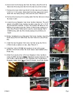
14. Using a strut spring compressor, unload the tension on the upper 

strut mount of the OEM coil assembly. Remove the upper shock 

retaining nut using 9/16” socket & slide the OEM strut out from the 

bottom of the OEM strut assembly. (See Arrow in Photo # 9)

15. Assemble the new Skyjacker strut by installing the new Skyjacker 

coil spring seat, new Skyjacker coil spring pad, & OEM bump stop 

on the new Skyjacker strut. (See Photo # 10).

16. Slide the new Skyjacker strut assembly in from the bottom & install 

the OEM rubber coil seat on top of the OEM coil. (See Photo # 11) 

Important Note:

 Be sure that the bottom shock eye is square with 

the two upper front studs on the OEM rubber mount. 

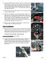
17. Install the new coil / strut assembly into the vehicle. Attach to the 

OEM upper mount using the OEM hardware.

18. Attach to the lower A-arm using the OEM hardware. 

“Ford Torque 

Specifications”

 for this bolt is 351 Ft. Lbs.

19. It will be necessary to have the OEM spindle pressed out of the 

OEM steering knuckle by a qualified machine shop. Once the 

      spindle is pressed out, apply anti-seize compound & press the 

      spindle into the new Skyjacker steering knuckle. (See Photo # 12). 


Note: 

A 10,000 lb shop press will be needed for this step.

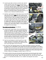
20. Attach the new Skyjacker steering knuckle to the lower A-arm ball 

joint (Torque to 111 Ft. Lbs) & upper A-arm ball joint (Torque to 85 

Ft. Lbs) using the OEM hardware. (See Photo # 13) Attach the outer 

tie rod using the OEM hardware. (Torque to 111 Ft. Lbs.) 

Periodically 

re-torque upper / lower ball joints & outer tie rod!


21. On the rearward side of the new Skyjacker steering knuckle, there is 

a new mounting location for the OEM ABS line. Using the 3/8” cable 

clamps & 5mm x 12mm bolts, attach the ABS line to this new 

      location.

I-F4621

Pg 5

Photo # 9

Photo # 10

Photo # 11

Photo # 12

Photo # 13

Содержание F4621A

Страница 1: ...visible Using a measuring tape measure the front rear both sides from the ground up to the center of the fender opening above the axle Record this information below for future reference Driver Side Front Passenger Side Front Driver Side Rear Passenger Side Rear IMPORTANT NOTES This lift is determined from the amount of lift to the front of the vehicle while only lifting the rear to a position leve...

Страница 2: ...E WASHER 8 HB F462 CM F462 CROSSMEMBERS ITEM DESCRIPTION QTY 18X150MMB 18MM X 150MM BOLT 10 9 4 34SAEW 3 4 SAE WASHER 8 18MMN 18MM 2 5TPI NYLON LOCKNUT 4 12X512FTB 1 2 X 5 1 2 FINE THREAD BLT 4 12SAEW 1 2 SAE WASHER 8 12FTN 1 2 20 FINE N I LOCK NUT 4 CS4530 CRUSH SLEEVE F462FCM S 1 CS3980 CRUSH SLEEVE F462RCM S 2 14X150MMBG5 14MM X 150MM 8 8 1 916SAEW 9 16 SAE WASHERS 2 14MMN 14MM NYLON INSERT LOC...

Страница 3: ...ack under the lower control arm s front cross member raise the vehicle Place jack stands under the frame rails behind the front wheel wells lower the frame onto the jack stands 2 Remove the front tires wheels using a 22mm socket Remove the brake caliper using a 13mm wrench See Photo 1 It will not be necessary to remove the brake line from the brake caliper Simply wire it out of the way until reass...

Страница 4: ...mm bolts washers nuts See Photo 5 Be sure to use the crush sleeves Part CS3980 along with the 18mm bolts between the OEM A arm mount 10 Before installing the new Skyjacker front cross member insert the crush sleeve Part CS4530 into the front frame rail See Photo 6 11 Install the new Skyjacker front cross member using the 18mm x150mm bolts washers nuts See Photo 7 12 Install the 14mm x150MM bolt wa...

Страница 5: ...8 Attach to the lower A arm using the OEM hardware Ford Torque Specifications for this bolt is 351 Ft Lbs 19 It will be necessary to have the OEM spindle pressed out of the OEM steering knuckle by a qualified machine shop Once the spindle is pressed out apply anti seize compound press the spindle into the new Skyjacker steering knuckle See Photo 12 Note A 10 000 lb shop press will be needed for th...

Страница 6: ... end towards the rear Attach the sway bar links to the lower A arms using the OEM hardware See Photo 15 25 With the front end complete See Photo 16 Install the tires wheels lower the vehicle to the ground Rear Installation 26 Raise the rear of the vehicle support the frame rails using jack stands Remove the rear shocks using a 15mm 18mm socket See Photo 17 Remove the rear u bolts using a 21mm sock...

Страница 7: ... add a leafs properly you must use two large C clamps to contain the elastic potential energy in a leaf spring when the center tie bolts are being removed Attach tighten a C clamp on each end of the leaf spring to hold the leaf spring assembly securely together Using locking pliers to hold the head of the two center bolts loosen remove With care slowly loosen remove the C clamps See Photo 22 33 In...

Страница 8: ...ings Have a qualified alignment center realign the front end to the factory specifications Retorque all the bolts after the first 100 miles Seat Belts Save Lives Please Wear Your Seat Belt Torque specificAtions Inch System Bolt Size Grade 5 Grade 8 5 16 15 FT LB 20 FT LB 3 8 30 FT LB 35 FT LB 7 16 45 FT LB 60 FT LB 1 2 65 FT LB 90 FT LB 9 16 95 FT LB 130 FTLB 5 8 135 FT LB 175 FT LB 3 4 185 FT LB ...

Отзывы: