background image

12

Electronic Controller

Service Manual

SERENE SC112N-A

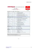
Parameter list - SC112N-A program 102

Revision:

2.0

Application

SC112G

Controller Type

SKOPE S4 EVO

Controller Model & Revision

PZSKC0H002K  (Rev 1.414)

SKOPE Part Number

ELZ11478-102

Setting

Unit

SET0

Min

Max

Probe Parameters

PS

22


F

0

200

Password (Read Only)

/2

4


C

1

15

Measurement stability (Applies to all probes)

/4

1


C

1

5

Select probe displayed

/5

0


C

0

1

Select °C/°F ( 0=°C ; 1=°F )

/6

0


C

0

1

Disable decimal point

/8

0

°C

C

-99.00

99.0

Display Offset (Only if /E > 0)

/9

0

°C

C

-40.0

/A

Minimum Display value (Only if /E > 0)

/E

1


C

0

50

Display Dampening Coefficient

/C1

3.5

°C

C

-50.0

50.0

Probe 1 Calibration Offset

/C2

0.0

°C

C

-50.0

50.0

Probe 2 Calibration Offset

/C3

0.0

°C

C

-50.0

50.0

Probe 3 Calibration Offset

Regulation Parameters

St

2.0

°C

F

r1

r2

Set point

rd

3.0

°C

C

0.0

19.0

DAY differential

r1

0.0

°C

C

-50.0

r2

Minimum set point value

r2

4.0

°C

C

r1

150

Maximum set point value

r3

1


C

0

1

Enable Auto Day/Night Mode Switching

r4

2.0

°C

C

-50.0

50.0

Night Mode set point delta (added to St)

r5

3.0

°C

C

0.0

19.0

Night differential

r6

90

hrs

F

0

90

Night Mode Start Delay (time period with no door openings)

r7

8

hrs

F

1

90

Night Mode Timeout (time period in night mode)

r10

0

hrs

C

0

24

Light Delay On Time after entering DAY mode

Cold Climate Protection Parameters

CCt

2.0

°C

C

0.1

20.0

Cold Climate Protection Temperature Delta

CCd

30

mins

C

0

199

Cold Climate Protection Delay

Pull Down Mode Parameters

Pt

127

°C

C

0

127

Pull-down Mode - Activation Temperature

Pd

250

hrs

C

0

250

Pull-down Mode - Maximum Duration

Compressor Parameters

c0

2

mins

C

0

200

Comp. and Fan start delay at power-up.

c1

6

mins

C

0

100

Minimum time between consecutive compressor starts

c2

5

mins

C

0

100

Minimum compressor off time

c3

0

mins

C

0

100

Minimum compressor on time

c4

15

mins

C

0

100

Compressor on time with duty setting

c5

1


C

0

1

Enable mains voltage protection (0 = disabled, 1 = enabled)  

Defrost Parameters

d0

0


C

0

1

Type of defrost ( 0 = Electric, 1 = Hot Gas)

dI

3

hrs

C

0

199

Defrost interval time (Time between defrosts)

d2

1


C

0

1

Run defrost interval timer only when compressor running

dt

6

°C

C

-50.0

127

Defrost Termination temperature

dP

60

mins

C

1

199

Maximum defrost duration

d4

0


C

0

1

Defrost request at power-on: (0 = no, 1 = yes)

d5

0

mins

C

0

199

Defrost delay on power-up (when d4=1)

d6

1


C

0

1

Display during defrost (0 = "dEF", 1 = Temperature at start of defrost)

dd

0

mins

C

0

15

Dripping time (compressor and fans stopped after defrost)

d8

0

mins

C

0

199

Bypass high temperature alarm after defrost or door opening

d9

0


C

0

1

Defrost priority over compressor protectors

d/1

-

°C

F

-

-

Probe reading on 2nd Input (read only)

Parameter

102

CPS1017-102-SET0

Last revised on

27-Oct-2020

Full List

SET0

Access 

Level

Range

Description

Electronic Controller Parameter Sheet

Page 1 of 2

Содержание Serene SC112N-A

Страница 1: ...Service Manual MAN80301 Rev 1 0 Mar 2021 SC112N A SERENE Four Glass Sided Chiller Type HSC112N Z156 from SKOPE...

Страница 2: ...site www skope com Trademark Infringement The SKOPE trademark on this product is infringed if the owner for the time being does any of the following Applies the trade mark to the product after their s...

Страница 3: ...Cycle 9 Lighting 9 Messages and Alarms 10 Controller Display 10 Programming the Electronic Controller 11 Parameters 11 4 Wiring Model SC112N A 14 Notes 15 5 Spare Parts Cabinet Assembly 16 Parts Cabi...

Страница 4: ...y 27 Refrigeration System Access 28 Refrigeration System Dismantling 29 Evaporator Fan 31 Condenser Fan 31 Power Supply and Surge Protector 32 Compressor 32 Compressor Electrics 33 Electronic Controll...

Страница 5: ...00a is a natural refrigerant that has a very low environmental impact Special service requirements are needed as R600a is a flammable refrigerant Safety hazards The main R600a safety hazards are Flamm...

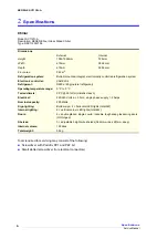
Страница 6: ...stem Bottom mounted integral electronically controlled refrigeration system Electronic controller CAREL S4 Refrigerant R600a 40g natural refrigerant Operating temperature range 0 C to 5 C Tested clima...

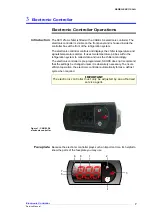
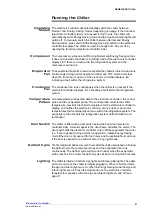
Страница 7: ...It uses two temperature probes within the refrigeration system to collect data and runs the chiller accordingly The electronic controller is pre programmed SKOPE does not recommend that the settings...

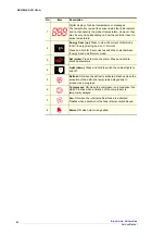
Страница 8: ...for 3 seconds to switch the chiller between Energy Save and Normal mode 3 Set mute Press to mute the alarm Press and hold to access parameters 4 Light down Press and hold to switch the cabinet lights...

Страница 9: ...s feed data to the electronic controller the control probe and the evaporator probe The control probe controls the chiller temperature provides the chiller temperature for the electronic controller to...

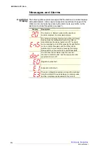
Страница 10: ...ler is in Energy Saving mode When in Energy Saving mode the temperature inside the chiller is moderated and the cabinet lights turn off The lights can be switched on and off by pressing the light butt...

Страница 11: ...up and Light down buttons to scroll the parameter codes and locate the required parameter Parameter categories can be identified by the initial symbol or letter of the code and the icon displayed on t...

Страница 12: ...eters CCt 2 0 C C 0 1 20 0 Cold Climate Protection Temperature Delta CCd 30 mins C 0 199 Cold Climate Protection Delay Pull Down Mode Parameters Pt 127 C C 0 127 Pull down Mode Activation Temperature...

Страница 13: ...ion A12 3 C 0 16 Number of cA alarm events to trigger manual reset CA alarm A13 24 hrs C 0 240 cA alarm counter reset delay A14 60 mins C 0 240 cA alarm reset delay A15 1 C 0 1 Lights switched OFF whe...

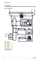
Страница 14: ...d Surge Protector BN BU GNYE BN BN BN BK BU BU BN M BU 12Vdc Power Supply N L M BK RD BU WH 12Vdc Power Supply N L RD BU BK RD RD BK All Cabinet Lighting Evap Temp Probe Cabinet Temp Probe BU Evaporat...

Страница 15: ...15 SERENE SC112N A Wiring Service Manual Notes...

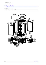
Страница 16: ...16 Spare Parts Service Manual SERENE SC112N A 5 Spare Parts Cabinet Assembly 1 1 2 2 3 3 4 4 5 6 6 7 8 9 10 11 12 13 14 15 16 16 17 17 18 19 20 21 5...

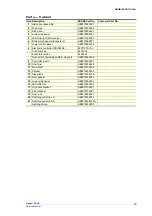
Страница 17: ...ic controller CAREL S4 ELZ11478 102 Control probe ELZ1255 Evaporator probe ELZ7644 Door switch including cable magnet HB0074091496 9 Controller insert HB0070204937 10 Shelf clip HB0070204928 11 Wire s...

Страница 18: ...18 Spare Parts Service Manual SERENE SC112N A Refrigeration System Assembly 1 2 3 4 5 6 7 8 8 8 9 10 11 11 11 12 13 14 15 16 16 16 17 19 18...

Страница 19: ...12Vdc power supply HB0071800202 7 Evaporator coil HB0070700492 8 Lower outer extrusion HB0070109356A 9 PTC starter HB0074000381FJ 10 Wanbao Compressor ETA110L HB0074000910 11 Adjustable foot HB007010...

Страница 20: ...ith four shelf clips which engage in the corner shelf support strips To adjust the cabinet shelves 1 Remove the shelves from the chiller 2 Remove the shelf clips from the four shelf support strips at...

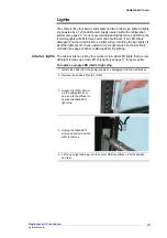
Страница 21: ...a the light switch on the electronic controller see page 9 before replacing LED strip lighting Interior lights The cabinet interior is lit by four vertical corner pillar LED lights Each corner pillar...

Страница 22: ...ee page 17 for spare parts To replace a bottom sign light 1 Isolate the chiller from the power supply by unplugging from the wall socket 2 Remove the lower bottom panel by undoing the three fixing scr...

Страница 23: ...out of shape after you fit it use a hair dryer to heat and reshape it Removing and Fitting Doors For ease of servicing the doors can be removed from the chiller To remove a door To refit a door Figur...

Страница 24: ...torsion bar 1 Isolate the chiller from the power supply by unplugging from the wall socket 2 Remove door from the cabinet see page 23 3 Refit door to cabinet see page 23 adjusting the tension via the...

Страница 25: ...ompressor oil Asphyxiation Refrigerant identification The cabinet rating label located in the upper inside of the cabinet states the refrigerant type In addition to this warning labels are fitted to h...

Страница 26: ...ration gauge set suitable for R290 flammable refrigerant Bullet valves line piercing valves suitable for 6mm tube Service vehicle Suitable for transporting flammable gas being HC refrigeration systems...

Страница 27: ...Verify basic requirements before servicing Refrigeration Unit Assembly Compressor Wanbao Compressor ETA110L Compressor capacity 250 Watts Refrigerant R600a Charge 40g Bottom sign lights cables Evapora...

Страница 28: ...upply by unplugging from the wall socket 2 Remove the front and back lower bottom panels by undoing the three fixing screws and sliding them down and remove the sign panel and decal from the sign 3 Re...

Страница 29: ...for a second person to hold the bottom refrigeration system while separating 1 2 3 4 Fixing screw Fixing screw Level Components and parts 1 bottom Compressor compressor electrics condensate tray cond...

Страница 30: ...e Components on level two can now be accessed 6 Remove the two horizontal struts from the sides of the refrigeration system by undoing the two fixing screws from each strut 7 Detach the mains flexible...

Страница 31: ...from the power supply separate the top cabinet assembly from the bottom refrigeration system and gain access to level two of the refrigeration system see page 29 2 Trace evaporator fan cable and unpl...

Страница 32: ...over 220 volts Ensure the voltage does not drop at start up If the voltage does drop ensure the refrigeration system has a direct power supply not from a multi box or extension cord To access the comp...

Страница 33: ...ated at the front of the chiller behind the lower bottom panel and is visible from the front of the chiller For information on operation and programming refer to the Electronic Controller section of t...

Страница 34: ...wn 3 The terminals at the rear of the electronic controller can now be accessed 1 Follow the steps above to access the rear of the electronic controller 2 Unplug the terminals from the rear of the con...

Страница 35: ...stem and gain access to level three of the refrigeration system see page 29 2 Gain access to the terminals at the rear of the electronic controller see page 34 3 Unclip and detach the control probe an...

Страница 36: ...e electronic controller Unplug from the controller 6 Attach the new evaporator probe cable to the terminals at the rear of the electronic controller and fit the cable following the same path as the or...

Страница 37: ...er faceplate Electronic controller displays Err indicating a refrigeration system error Arrange service call Failed LED light Arrange service call Product is too warm Frequent door opening Limit door...

Страница 38: ...SKOPE Contacts SKOPE Industries Limited A B N 73 374 418 306 AU 1800 121 535 NZ 0800 947 5673 skope skope com www skope com...

Отзывы: