background image

951-150-029-EN

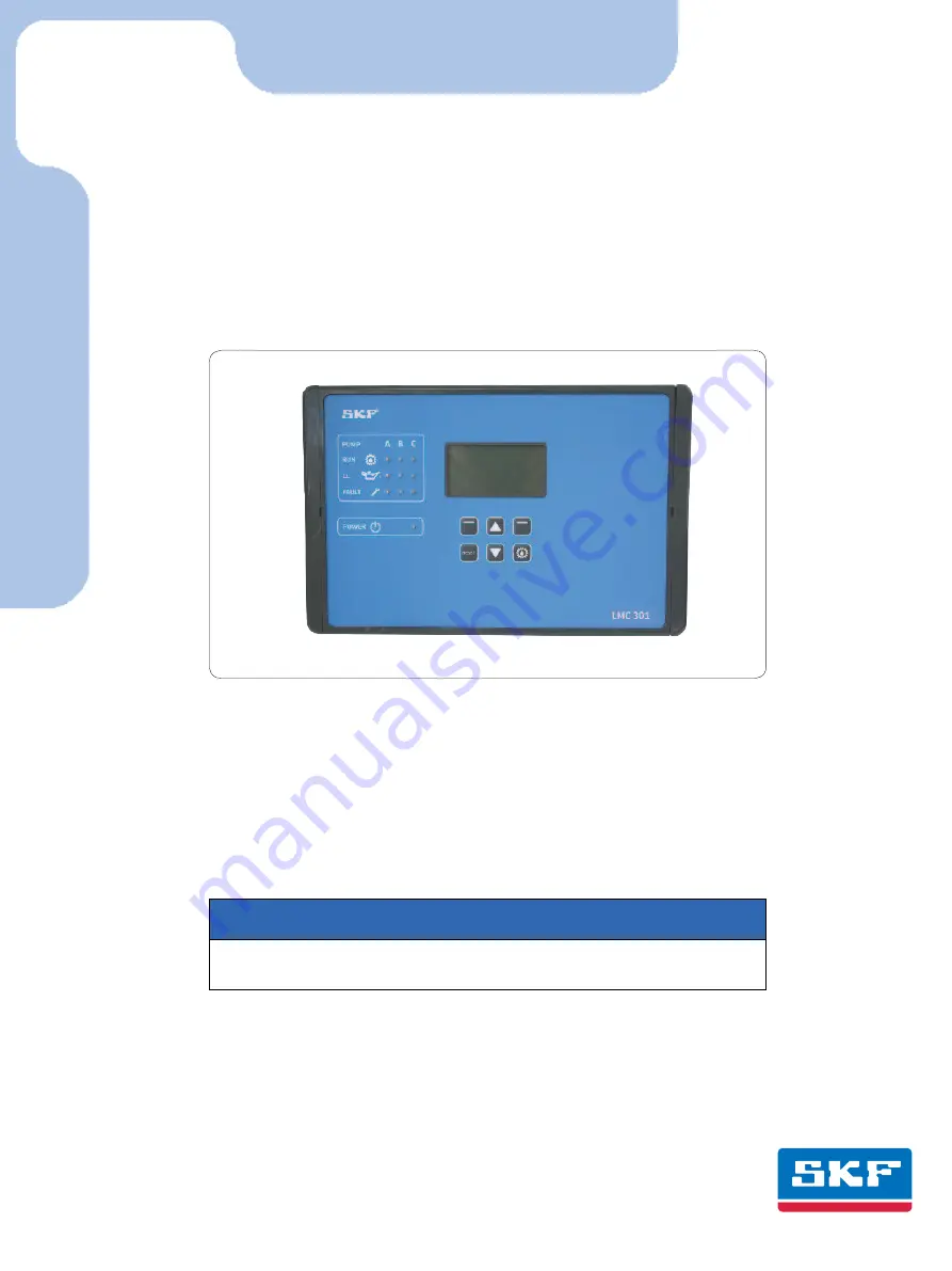
This description is intended as an overview of installation for the LMC 301 Lubrication 
Monitor Controller. It does not replace the assembly instructions for the LMC 301 controller. 
These are contained on the enclosed USB stick. The assembly instructions can be ordered in 
paper format from SKF Lubrication Systems Germany GmbH or Lincoln Industrial, One 
Lincoln Way, St. Louis, MO 63120-1578  USA. 
In case of discrepancies between the assembly instructions and the Quick Guide, the information 
in the assembly instructions takes precedence.

for control of up to three pumps, each with an SKF Single Line / Progressive  
and Dual Line centralized lubrication system containing one to three main lines.

Lubrication Monitor Controller 

of series LMC 301

Quick Setup/Installation Guide

Version 03

ATTENTION!

The comprehensive assembly instructions (see page 2) are included on the enclosed USB stick 
and can be downloaded from our homepage


http://www.skf.com/LMC301/

.

Содержание LMC 301 Series

Страница 1: ...y St Louis MO 63120 1578 USA In case of discrepancies between the assembly instructions and the Quick Guide the information in the assembly instructions takes precedence for control of up to three pumps each with an SKF Single Line Progressive and Dual Line centralized lubrication system containing one to three main lines Lubrication Monitor Controller of series LMC 301 Quick Setup Installation Gu...

Страница 2: ...13 5 2 2 Main menu 13 5 2 3 General setting options 14 5 2 4 Menu structure for system coniguration 15 5 3 Coniguration of several IO boards to master slaves 16 5 3 Menu navigation for operators without password access 17 5 4 Menu navigation for local admins with password access 18 6 System coniguration 19 Single Line Menu navigation for system coniguration 6 1 Single Line pump settings with Super...

Страница 3: ...anisms must be removed they must be installed im mediately following conclusion of work and checked for proper function o Any malfunctions that occur must be resolved according to responsibility The supervisor must be notified immediately in case of malfunctions outside one s indi vidual scope of responsibility o Wear personal protective equipment o Observe the relevant safety data sheets when han...

Страница 4: ...l up to three pumps each with a one to three zone one to three main lines SKF Centralized lubrication system LMC 301 designs 86501 and 86503 IO module are powered via 100 to 240 VAC mains provided by the customer They must be connected in accordance with DIN VDE regulations LMC 301 designs 86500 and 86502 IO module are powered via 24 V DC The technical information contained in these instructions m...

Страница 5: ...vel reduce input value Pressing triggers an interim lubrication By briefly pressing follows the choice of an additional lubrication Actuations while in configuration mode are ignored RESET Long pressing 3 seconds stops all systems or resets an error message Long pressing acknowledges and clears error messages RESET P U M P A B C RUN LL FAULT POWER RESET LMC 301 Display elements of control screen S...

Страница 6: ...ump zone e g P1Z1 Press the arrow key again to display the activated inlets of the currently selected pump zone Press the arrow key again to display the activated outlets of the currently selected pump zone Press the additional lubrication key shortly to carry out an additional lubrication of the entire system respectively of the activated zones P1Z1 pump 1 zone1 to max max P3Z3 pump 3 zone 3 Over...

Страница 7: ...ands PG M20 without UL certiication Characteristics design Electronic consuming Iternal fuse LMC Controller 3 A Input AC Input voltage 100 240 VAC 50 60Hz customer Fusing slow 4 A 100 240 VAC Input DC 2 3 Input voltage 24 V DC 10 custermer Fusing slow 10 A Output rating relays Connection directly to the relay 01 02 100 240 VAC max 15A Connection directly to the relay 01 02 24 VDC max 15A Output te...

Страница 8: ...LMC 301 4 3 Assembly of the control unit See Figure 1 The controller unit is installed using 4 cheese head screws of thread size M4 If M4 tapped bores are used to fasten the unit the screws must have a minimum length of 15 mm Fastening material to be provided by the customer o Cheese head screws with hexagon socket 4x acc to DIN6912 M4x 8 8 o Washers 4x acc to DIN EN ISO 7090 4 200HV o Self lockin...

Страница 9: ...rol unit Conductors or compo nents within the device must not be touched under any circumstances See Figures 4 and 5 4 5 Line routing The lines are laid through cable glands at tached on both sides and on the bottom The attached cable glands are provided for the following lines optional Left side cable glands Power supply Master Slave connection optional Right side cable glands Relay outputs load ...

Страница 10: ... VDC output for mainboard 7 USB port external Not for User 8 DIP switch addresses 4 8 9 RESET switch Hardware Reset 10 Fuse FK1 3A 11 Load switching relay 2x X5 4 7 5 12 PE Ground terminals for relay outputs X6 4 7 4 Connections on mainboard 24 VDC design Fig 5 Cable glands for power supply interface Cable glands for valves motor Legend to Figure 5 Item Description BA Chapter 1 Power supply X1 4 7...

Страница 11: ...3 O 2 O 2 O 1 O 1 O 8 O 8 O 7 O 7 O 6 O 6 O 5 O 5 O O u t p u t Terminals O3 to O8 max 8 A Connections in conjunction with load switching relay max 8 A X4 ATTENTION You can run each terminal block 4 1 or 4 2 only with one operating voltage 24VDC or 100 to 240 VAC Do not mix 2 different voltages together on 1 terminal block 4 7 4 Load switching relay see Figures 4 5 item 11 and Fig 8 Proposal Load ...

Страница 12: ... plus signal 4 8 Adding an additional IO connection to RS485 interface see Figures 4 5 item 8 see Figures 13 14 ATTENTION A separate address must be assigned to each IO board To differentiate between multiple IOPCBs in an RS485 daisy chain each IOPCB needs its own address This can be set in the binary code using the DIP switch address switch If all four DIP switches are set to top the address is 1...

Страница 13: ... Connect the USB cable Fig 15 2 1 Install the controller unit Chapter 4 3 Open the controller unit Chapter 4 2 Connect the USB cable 2 from the laptop on the inside of the controller lid 1 and turn on the power supply Start the LMC 301 software The description of the PC configuration is included with the software Configure according to the included de scription for configuration on the PC 5 2 Coni...

Страница 14: ...ch Press control key Select Use down up arrow key to select the lan guage English Deutsch Press control key Save 4 Use up arrow key to select the Unit Settings menu item Imperial Metric Press control key Select Use down up arrow key to select Unit Set tings Imperial Metric Press control key Save Press control key Back You will return to the User settings menu Login settings Enter Set PassWord loca...

Страница 15: ...ollowing settings can be made o Amount of pumps o Setting the pumps o Set Params to Default Main menu Login settings User settings Device settings Pump 1 Timings System coniguration Information System coniguration Lubrication will be stopped Continue Yes No System coniguration Amount of pumps Setting the pump Set Params to Default ATTENTION SKF Service menu This level is password protected and can...

Страница 16: ...st be sepa rate for each board Connection is made on the respective board see page 11 Fig 9 o The maximum admissible connected load of each board is 3 A o In case of different potential free outputs make sure to use an adequate connection line and a corresponding connection dia meter see chapter 4 7 3 o For each connection line the customer must provide a correspondingly designed back up fuse ON 1...

Страница 17: ...ation HW FW Version Hours of Operating Error history Serial Number HW FW Version Hardware version Firmware version Hours of operation Cumulated operating Time Error history No 1 Serial Number Serial Number 0 0 0 0 0 0 0 0 Zone 1 Settings Lube load Normal Cycle Set Heavy Cycle Set Zone 2 Settings Lube load Normal Cycle Set Heavy Cycle Set Login settings Enter Password Set PW local admin Set PW Supe...

Страница 18: ...Login settings enabled disabled Local User Old Password 0000 New Passwort 0000 Pump 1 Timings Zone 1 Settings Zone 2 Settings Zone 1 Settings Lube Load normal Cycle Set Heavy Cycle Set Normal Cycle Time 0000 00 00 Heavy Cycle Time 0000 00 00 Lube Time 00 00 00 Holding Time 00 00 s Zone 2 Settings Lube Load Normal Cycle Set Heavy Cycle Set Normal Cycle Time 0000 00 00 Heavy Cycle Time 0000 00 00 Lu...

Страница 19: ... Type normally closed normally open disabled Output No 1 02 O Inputs Input LL Type disabled transducer 1 6V transducer4 20 mA transducer 0 20mA transducer 2 10V transducer 0 10V normally open normally closed Eingang Nr Leer Nr 1 03 DI Timings Filling Timeout 00 00 00 Detection LL Time 10 Motor Protection Motor Protection Type normally open normally closed disabled Input No 1 04 AI Relief Settings ...

Страница 20: ...t No 1 Typ normally open normally closed disabled Eingang Nr 1 1 08 DI Amount of pumps Amount of pumps 1 pump 2 pumps 3 pmps Login settings User settings Device settings Pump 1 Timings System configuration Informationen Main Menu System configuration Amount of pumps Pump 1settings Set Params to Default Pump 1 settings Pump settings Zone 1 Settings Zone 2 Settings Zone 3 Settings Zone 1 Settings Cy...

Страница 21: ...Filling disabled Lube Limited By LL Lube Cycles LL Pump time disabled Alarm Output Type normally closed normally open disabled Output No 1 02 O Inputs Input LL Type disabled transducer 1 6V transducer4 20 mA transducer 0 20mA transducer 2 10V transducer 0 10V normally open normally closed Input No LL 1 03 DI Timings Filling Timeout 00 00 00 Detection LL Time 10 Motor Protection Motor Protection Ty...

Страница 22: ...ount of pumps 1 pump 2 pumps 3 pmps Login settings User settings Device settings Pump 1 Timings System configuration Informationen Main Menu System configuration Amount of pumps Pump 1settings Set Params to Default Pump 1 settings Pump settings Zone 1 Settings Zone 2 Settings Zone 3 Settings Zone 1 Settings Cycle Control Lube Control Post Sprayer Alarm Login settings Enter Password Set PW local ad...

Страница 23: ...e Fact Set Continue Login settings User settings Device settings Pump 1 Timings System configuration Information Main Menu Login settings Enter Password Set PW local admin Set PW Supervisor Enter Password Please enter Password to continue 0000 Password correct You are logged in as Supervisor Login settings Login settings System configuration Amount of pumps Pump 1 settings Set Params to Default Re...

Страница 24: ...pen Input No A 1 02 AI Input No B 1 01 AI Minimal Valve 0000 PSI Maximal Valve 0000 PSI Min abs Pressure 0000 PSI Max abs Pressure 0000 PSI Min dif Pressure 0000 PSI Max dif Pressure 0000 PSI Note Additional buttons in transducer setting Monitoring Time 00 00 00 Holding time 00 00 00 Lube Control Time Proximity Sensor Amnt of Prox Sensor 2 Input No 1 Type normally closed normally open disabled Cou...

Страница 25: ...abled Input No 1 06 DI Lube Load Input Type normally closed normally open disabled Input No 1 07 DI Cycle settings Lubrication intervals Timings Version of driving Time interval of lubrication Operation of Release Counter Operation of the zone control and allocation Output Type normally closed normally open disabled Output No 1 03 0 Valve A Output Type normally closed normally open disabled Output...

Страница 26: ...cle Counts 0000 00 00 000 Release Counter Input Type normally closed Counter normally open disabled Input No 1 06 DI Lube Load Input Type normally closed normally open disabled Input No 1 07 DI Cycle settings Lubrication intervals Timings Version of driving Time interval of lubrication Operation of Release Counter Operation of the zone control and allocation Input Type normally closed normally ope...

Страница 27: ...0000 00 00 000 Release Counter Input Type normally closed Counter normally open disabled Input No 1 06 DI Lube Load Input Type normally closed normally open disabled Input No 1 07 DI Cycle settings Lubrication intervals Timings Version of driving Time interval of lubrication Operation of Release Counter Operation of the zone control and allocation Output Type normally closed normally open disabled...

Страница 28: ...ter consulting with and receiving written approval from SKF SKF is a registered trademark of the SKF Group SKF Group 2016 The contents of this publication are the copyright of the publisher and may not be reproduced even extracts unless prior written per mission is granted Every care has been taken to ensure the accuracy of the information contained in this publication but no liability can be acce...

Отзывы: