1
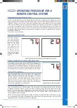
Temperature indication Display
With the system in
the “OFF” position,
press the Thermostat
Key and the Mode
Key at the same
time. Look at the
LCD screen on the
Transmitter to veri-
fy that a °C or °F
is visible to the
right of the Room
Temperature display.
(Fig. 7)
Fig. 7:
Remote Control display in Farenheit and Celsius.
OPeratinG PrOcedUre fOr a
remOte cOntrOl system
Turning ON the Appliance
Press the ON/OFF Key on the Transmitter. The Transmitter
display will show all active Icons on the screen. At the same
time the Receiver will command the DFC board to start the
ignition process. Once the pilot flame is proven the DFC
board will open the main valve outlet and the appliance
main burner will ignite. A single “beep” from the Receiver
will confirm reception of the command.
Turning OFF the Appliance
Press the ON/OFF Key on the Transmitter. The Transmitter LCD display will only show the room
temperature and Icon (Fig. 8). At the same time the Receiver disconnects will command the DFC
board to turn off the burner. Depending on the system model (IPI or CPI) the pilot may shut off
(IPI) or remain lit (CPI) and the appliance burner turns OFF. A single “beep” from the Receiver con-
firms reception of the command.
NOTE: if the Continuous Pilot ignition mode is selected, the Pilot ON Flame will remain. To also
turn it completely OFF, switch the appliance into Intermittent Pilot ignition mode, so set the IPI/CPI
Pilot Mode Switch to the IPI position (switch opened).
Initializing the System for the first time
Install the 4 AA batteries into the receiver battery bay. Note the polarity of the battery and insert
into the battery bay as indicated on the Battery cover (+/-). Place the 3 position slider switch in the
“REMOTE” position. (fig. 3) Insert the end of the paper clip or similar object into the hole marked
“PRG” on the Receiver front cover (fig 3). The Receiver will “beep” three (3) times to indicate that
it is ready to synchronize with a Transmitter. Install the 3 AAA type batteries in the Transmitter
battery bay, located on the base of the Transmitter. With the batteries already installed in the
Transmitter, push the ON button. The Receiver will “beep” four times to indicate the Transmitter’s
command is accepted.
The system is now initialized.
Setting the Appliance into Continuous Pilot ignition mode
If installed on the wirings, set the IPI/CPI Pilot Mode Switch
to the CPI position (switch closed). At that point the DFC igni-
tion board will immediately complete the ignition sequence
for the Pilot Flame, and then will remain with the Pilot Flame
ON, waiting for a command to ignite the Main Burner Flame.
Fig. 8:
Remote Control display.
0_I00_gtmf_cat_only 0-1 1
1/0/00 1.1.1


